Overview
In this assignment, you’ll create a scalable, customizable parametric structure that could serve as the basis for many different architectural forms.
You can use Dynamo or Grasshopper (choose one) to model your design, then demonstrate how you can parametrically scale your design for different uses.
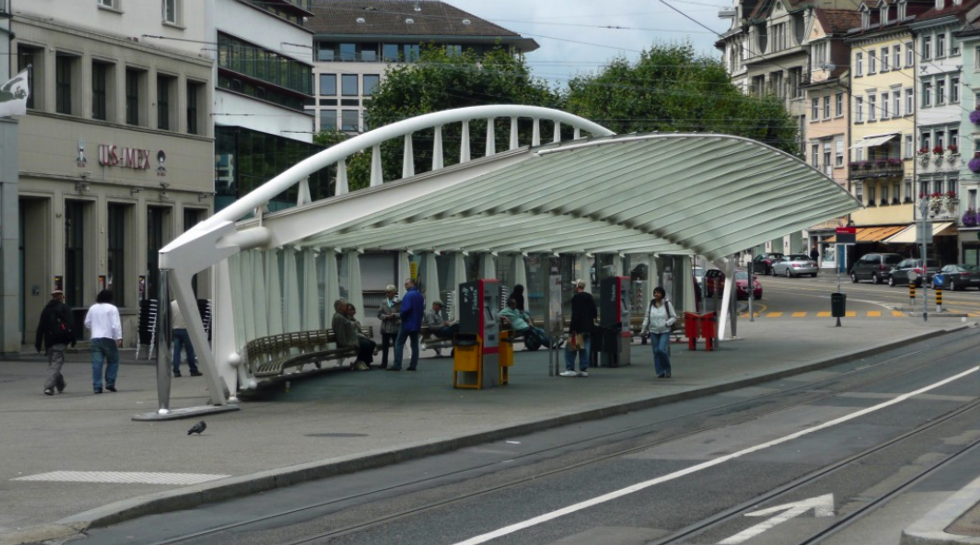
Your structure should provide partial shelter from the sun and rain – for example:
- a bus stop or train platform
- a bandstand or stage cover
- a covered walkway or arcade
Examples for Inspiration


As you develop your Dynamo or Grasshopper graph, exhibit good programming practice by:
- laying out your nodes diagrams very clearly
- creating groups for related nodes
- adding helpful comments in the group titles


Steps to Complete
Stage 1 — Modeling a Parametric Structure (for 2 or more units)
Step 1 — Planning
- Start by planning and sketching your design ideas. Think about:
- What is the overall form and shape of your structure?
- Choose a form that can be stretch linearly (along a straight line or a curve).
- DO NOT choose a radial form (one that is defined as a series of circles or radial lines).
- Choose a form that can be adjusted parametrically. You’ll want to provide inputs to:
- make it longer
- make it taller
- make it wider
- change the curvature and/or length of the main controlling curves
- change the frequency and/or amplitudes of any wave curves
- What controlling geometry (lines or curves)will drive the overall form and the placement of the components?
- What components will you use to model the elements your structure?
- In Revit: Using Adaptive Components or Sweeps for Beams and Adaptive Panels
- In Rhino: Using Grasshopper Sweeps for Beams and Grasshopper Panels
As you decide on the overall form for your shelter structure, think carefully about how the geometry can be modeled and the overall complexity of the form that you’ll be creating. While it’s tempting to imagine how these tools can be used to create truly fantastic forms, for the purposes of this assignment, you’ll want to be pragmatic about the time you have available to explore and model that form.
Step 2 — Define the Controlling Geometry (Lines or Curves ) and Use Them to Place the Structure’s Beams and Panels
- The underlying, controlling geometry will typically be defined by a series of lines or curves, then creating placement points along those curves.
- You’ll be using this controlling geometry to place:
- Structural rib or beam elements that support the shelter.
- Panels -- surfaces that provide a protective skin for some portion of the shelter.
- For the Adaptive Components, consider using one of these for simplicity:
- Tube - 3pt - Uniform (Point1Radius)
- Tube - 3pt - Tapered (Point1Radius, Point3Radius)
- For the Adaptive Panels, start by using:
- Rect_Seamless Panel-4pt
- For the rib or beam elements, you can create a profile in Rhino, then use Grasshopper nodes to sweep it along a path.
- For the panel elements, you can use nodes from the Lunchbox for Grasshopper package to subdivide the surface of your shelter into a series of rectangular panels, then create surfaces within each of these panels.
Tips for Dynamo Modeling
If you’re using Dynamo to model your shelter design in Revit, you can use pre-defined Adaptive Component and Adaptive Panel families to create the Revit elements. You’ll find a collection of commonly used adaptive component and adaptive panel families in the CEE 120C/220C Shared Library.
Tips for Grasshopper Modeling
If you’re using Grasshopper to model your shelter design in Rhino, you’ll follow a similar workflow, but you’ll need to generate the forms using nodes within Grasshopper:
Step 3 – Provide Ways to Parametrically Resize or Rescale Your Structure
- Your design should be resizable/scalable to adapt to a wide range of potential applications.
- Provide inputs that will allow you to easily change:
- the length or your structure by entering a new parameter value or dragging a slider to adjust the controlling geometry (lines or curves).
- the height of your structure overall or at specific points.
- the width of your structure overall or at specific points.
- the curvature and/or length of the main controlling curves.
- the frequency and/or amplitudes of any wave curves.
Step 4 – Provide a Way to Change the Number of Beams and Panels
- Another aspect of parametric flexibility to explore is providing ways to change the number of beams and panels placed using your controlling geometry.
- Provide inputs that will allow you to easily change or flex:
- the number of structural supports – the columns, beams, ribs, or trusses.
- the number or size/spacing of the panels on the shelter surface.
Finishing this Stage
- Save your files for this stage of the assignment using a file name that ends with “_Stage1”
- Save a screenshot showing your model geometry at the end of this stage.
Stage 2 - Transforming Your Geometry (for 3 or more units)
Step 1 – Add the Ability to Dynamically Change the Controlling Geometry
- Use the mathematical capabilities available in Dynamo or Grasshopper to add some parametric flexibility to one of the controlling lines/curves that define to your structure.
- Implement a mathematical transformation — for example transforming a simple line or curve into a sine or cosine wave with parameters controlling the wave amplitude or number of waves.
Step 2 — Flex Your Form Using the New Parameters
- Adjust the new input parameters to explore the impact of changing these inputs.
- Test the limits:
- What happens if you minimize these parameters?
- Can you return to the shape of the original form?
- What happens if you maximize these parameters?
- How far can your form be reshaped?
- Does your form break if flexed too far?
- What happens if these parameter go negative?
- Do negative values create a new, interesting, or unexpected shape?
- Do you need to impose any limits or constraints on the parameters to prevent errors in your modeling logic?
Finishing this Stage
- Save your files for this stage of the assignment using a file name that ends with “_Stage2”
- Save a screenshot showing your model geometry at the end of this stage.
Stage 3 - Applying Your Form at Different Scales (for 4 units only)
Step 1 – Reimagine Your Structure
- Imagine how your parametric logic could be adapted to create a structure at a very different scale that suits an entirely different purpose.
- If you’ve designed a structure with a small scale — for example, a bus stop or small pavilion — think about how this same logic could be applied to create a much larger scale structure.
- Similarly, if you’ve designed a structure with large scale — for example, an arena or convention hall — think about how this same form could be resized to a create useful, smaller scale structure.
Step 2 – Illustrate Your Form at Multiple Scales
- Implement your proposed design illustrating how your node logic can be applied to create useful structures at any scale:
- Small Scale — length around 30 feet.
- Medium Scale — length around 150 feet.
- Large Scale — length around 400 feet.
Finishing this Stage
- Save three screenshots showing your model geometry at the end of this stage — one for each scale:
- Small scale
- Medium scale
- Large scale
Submit
- Please create a folder named “Module 3” within your personal folder in our Autodesk Construction Cloud project.
- Then, upload these items to your Module 3 folder using the web interface:
- Your Revit project (.RVT) file and Dynamo graph (.DYN) file for each stage of the assignment.
- Or, your Grasshopper (.GH) file for each stage of the assignment.
- Create a link to your Module 3 folder:
- Right-click on the Module 3 folder in the file tree (at the left side of the interface) and choose Share from the pull-down menu.
- Choose Share with Project Members, then switch to the Link tab.
- Click the Copy button to copy the link to your clipboard.
- Create a new posting on this Notion page — Design Journal Entry: Give Me Shelter — including:
- A screenshot of your model geometry from each part of the assignment that you completed:
- For 2 or More Units: Modeling a Parametric Structure
- For 3 or More Units: Transforming Your Geometry
- For 4 Units: Applying Your Form at Different Scales
- A few sentences describing your modeling approach
- A brief description of your design outlining the parameters that can be used to flex and dynamically change your structure
- The link to your Module 3 folder in our Autodesk Construction Cloud project.