Enter (or choose) your name in the Your Name field above.
Then, describe your design inspirations and big feature ideas using text , images, web links, movies... Whatever media works best to express your ideas!
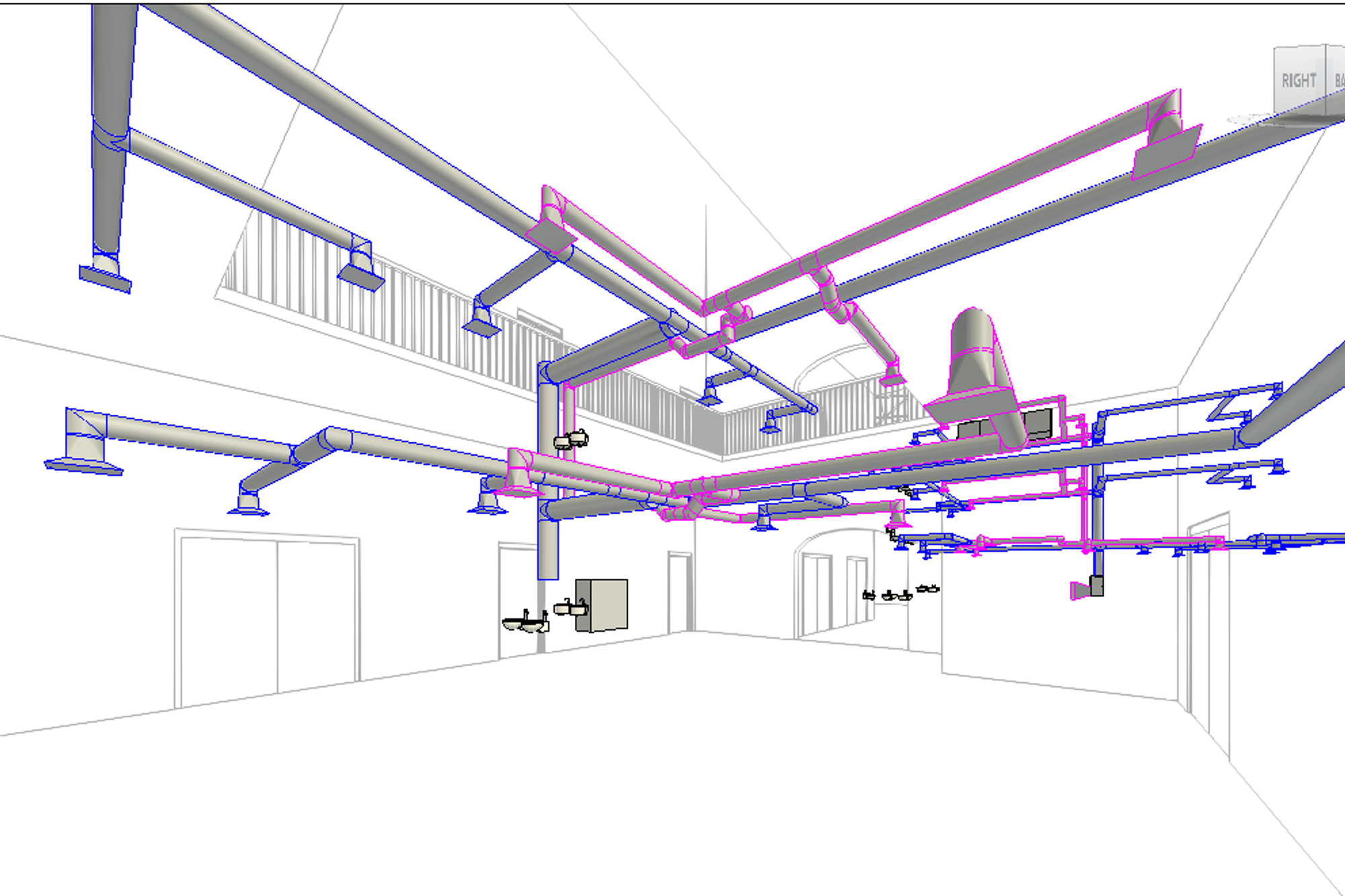
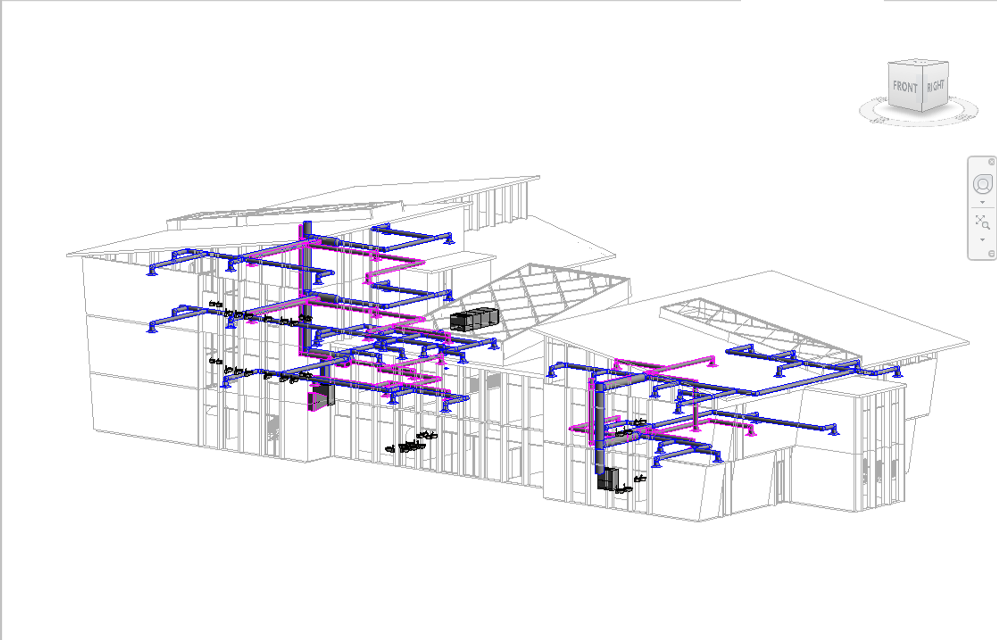
3D View of HVAC + Architectural Model:
Overview of HVAC Strategies:
I selected an air-based delivery system for the HVAC model. The mode of air delivery chosen is multi-zone variable air volume (VAV) distribution to allow for simultaneous conditioning of varied spaces within a single system. Below are the primary and secondary systems for the modeled HVAC package:
- Primary System: Split Air-to-Water Source Heat Pump with AHU on the roof
- Secondary Systems:
- Active Radiant Panels/Sails/Rafts in the exhibition spaces, classrooms, offices, conference rooms, etc.
- VAV w/induction reheat in the food prep, and kid’s zone
- with additional air filtration infrastructure to account for the greater airflow demands in these high and dynamic occupancy spaces
- Hybrid ventilation in the atrium cores and perimeter spaces
- atrium roof fans to induce the stack effect
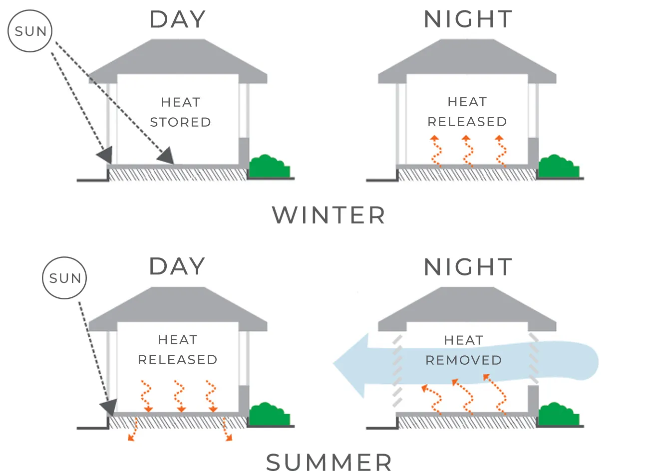
- Thermal mass flooring in the atrium spaces, cafe, and egress shafts for heat storage and dissipation
I was motivated to craft an HVAC package that was simple and capable of complimenting the architectural and structural design motifs. My goal was to design an HVAC system that did not exist to be hidden, but could be outwardly expressed and be woven into the visual experience of users.
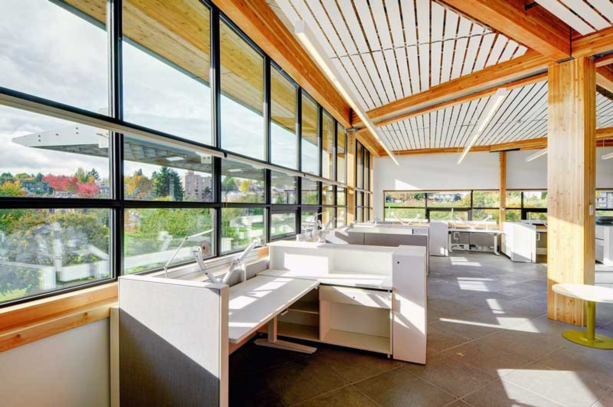
Radiant panels: Radiant panels are a chilled ceiling technology that can provide heating and cooling. They are typically configured as flat metal panels or curved sails with water pipes that circulate chilled or hot water to the pipes to facilitate thermal conditioning of the occupied spaces. The energy transfer from the water to the metal panel is radiated downwards toward the building occupants. Radiant panels are beautifully expressive, modular, and customizable, and hence advantageous for meeting various applications. The intention with selecting radiant panels was to allow the HVAC diffusers to integrate with the existing beam systems and fit between the beam elements rather than having to punch through them. This could be done by suspending the panel elements. This would create the effect of a mosaic ceiling with interesting interplay between the natural wooden structural elements and the metallic mechanical systems. Below are inspiration images showing the complimentary nature of radiant panels in relation to architectural and structural design
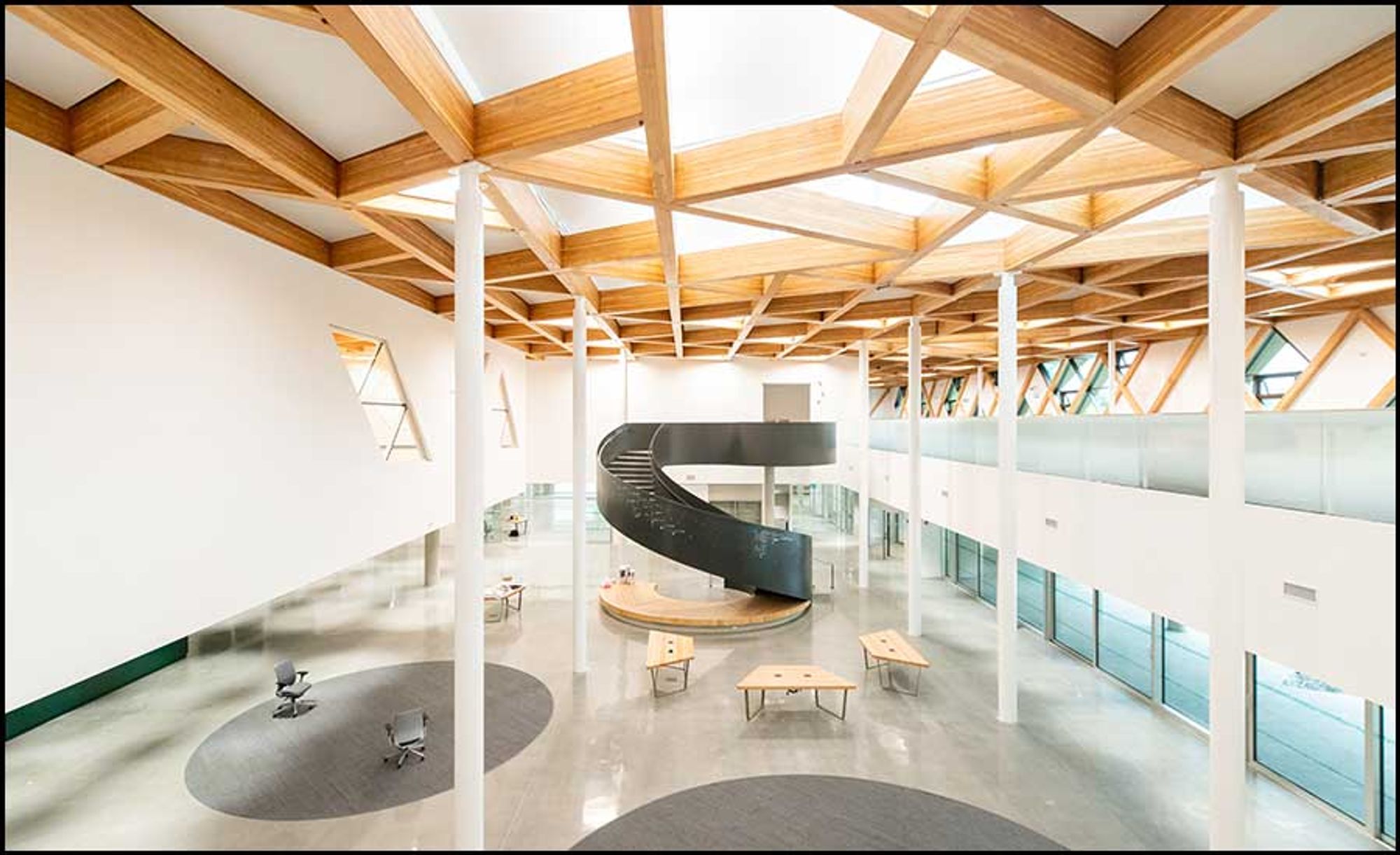
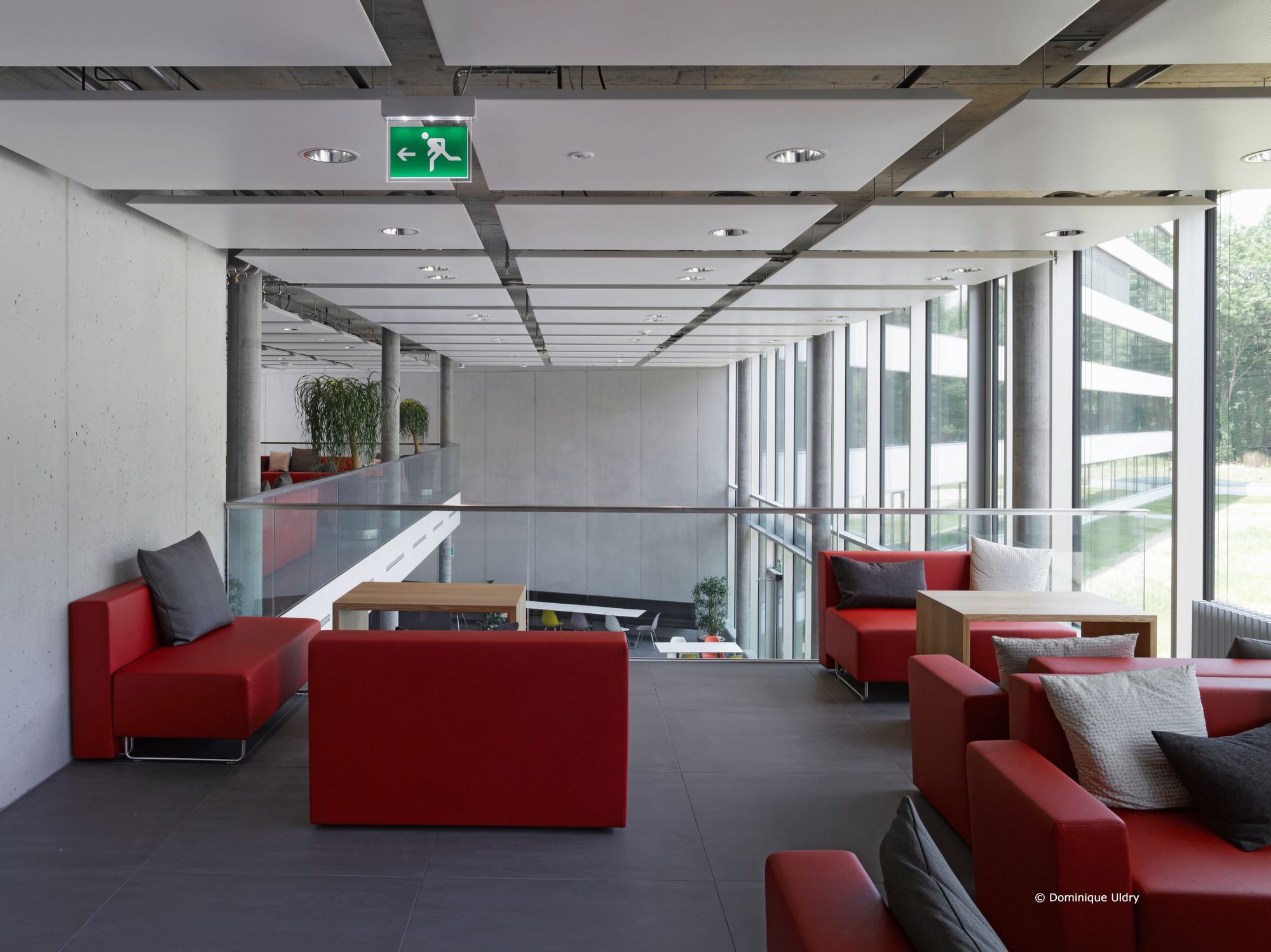

Beyond the visual realm, it was important to develop an HVAC system that would be capable of meeting the conditioning needs of the various spaces in an efficient manner. Radiant panels have been documented to be more energy-efficient than traditional heating systems. They emit heat directly to objects and people in the room, rather than conditioning the air itself, which drives the high efficiency.
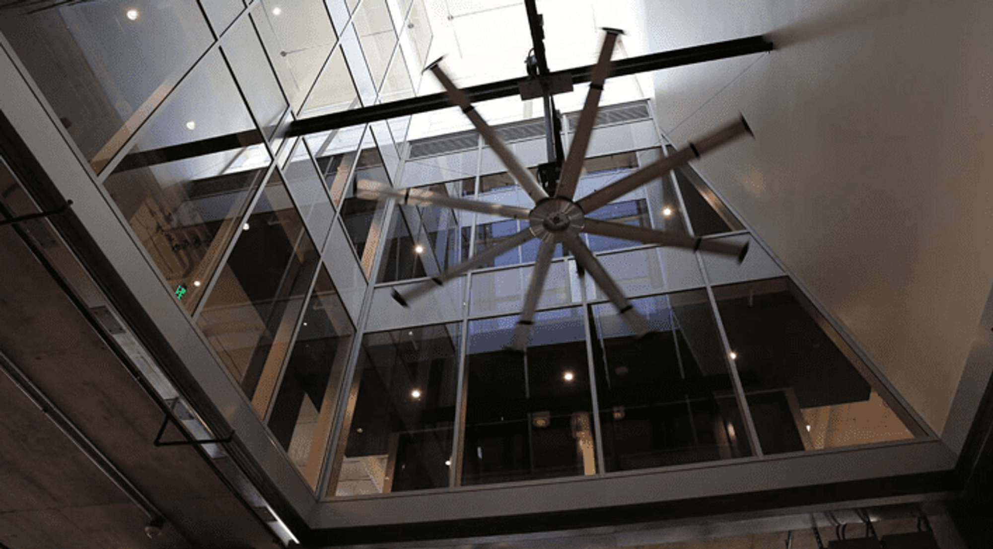
Hybrid Ventilation with VAV and Operable Envelope and Roof elements: Do reduce the amount of mechanical ventilation required and thus reduce energy usage, I will compliment the HVAC system with hybrid ventilation leverage single-side and induced stack effect ventilation during periods of high wind conditions.
Thermal Mass Flooring: these elements harness energy from solar gains to provide passive heating and cooling in the atrium and common spaces.
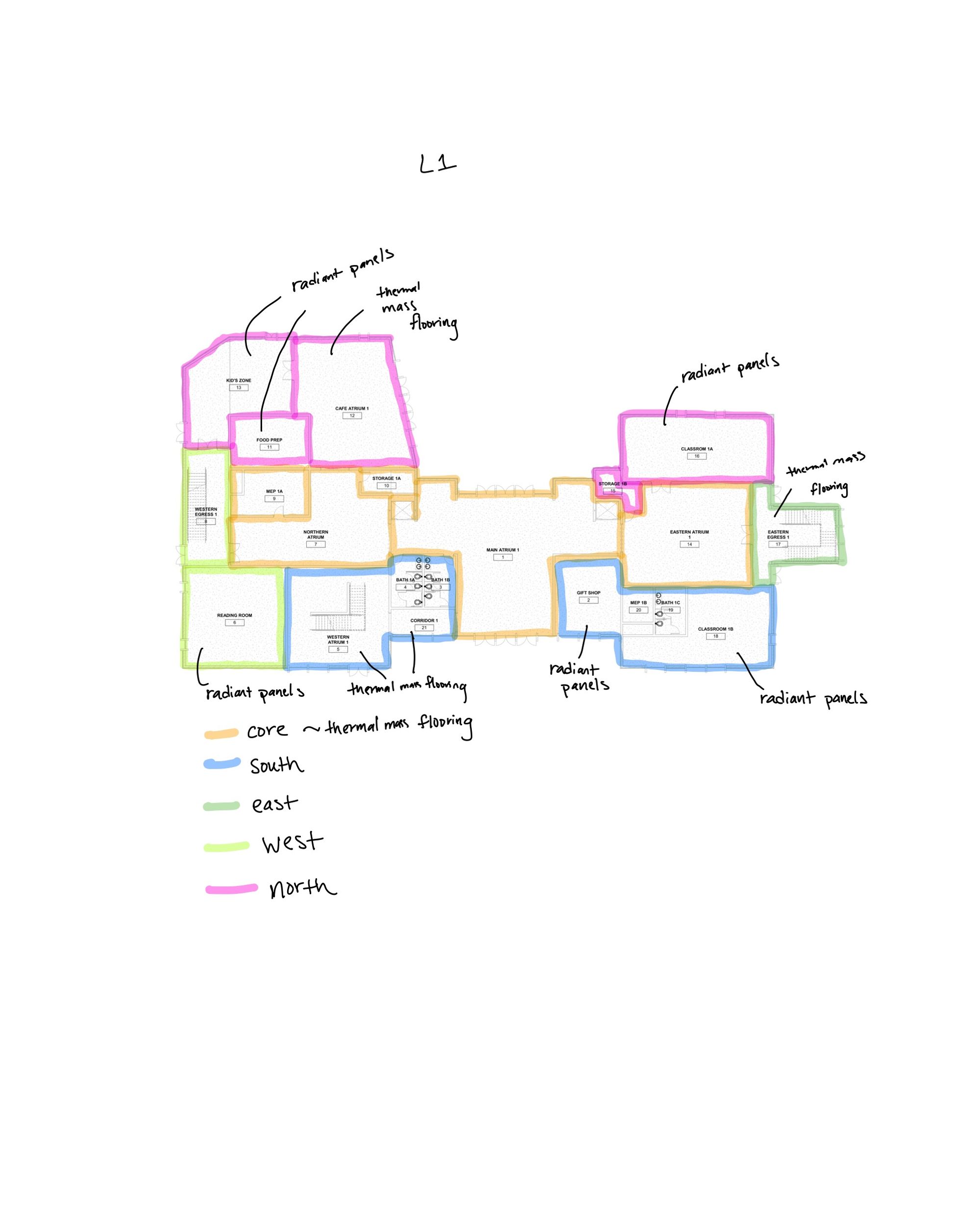
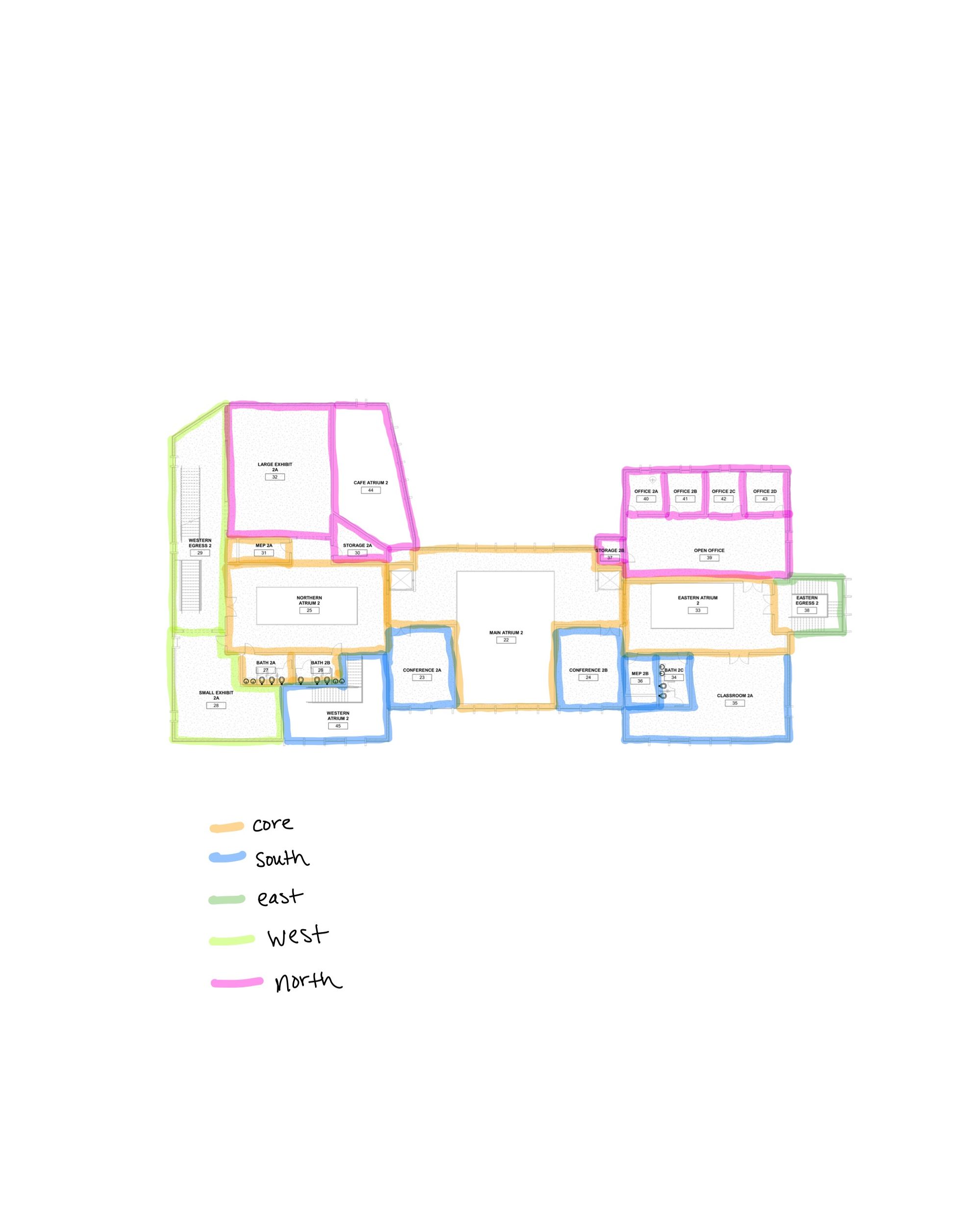
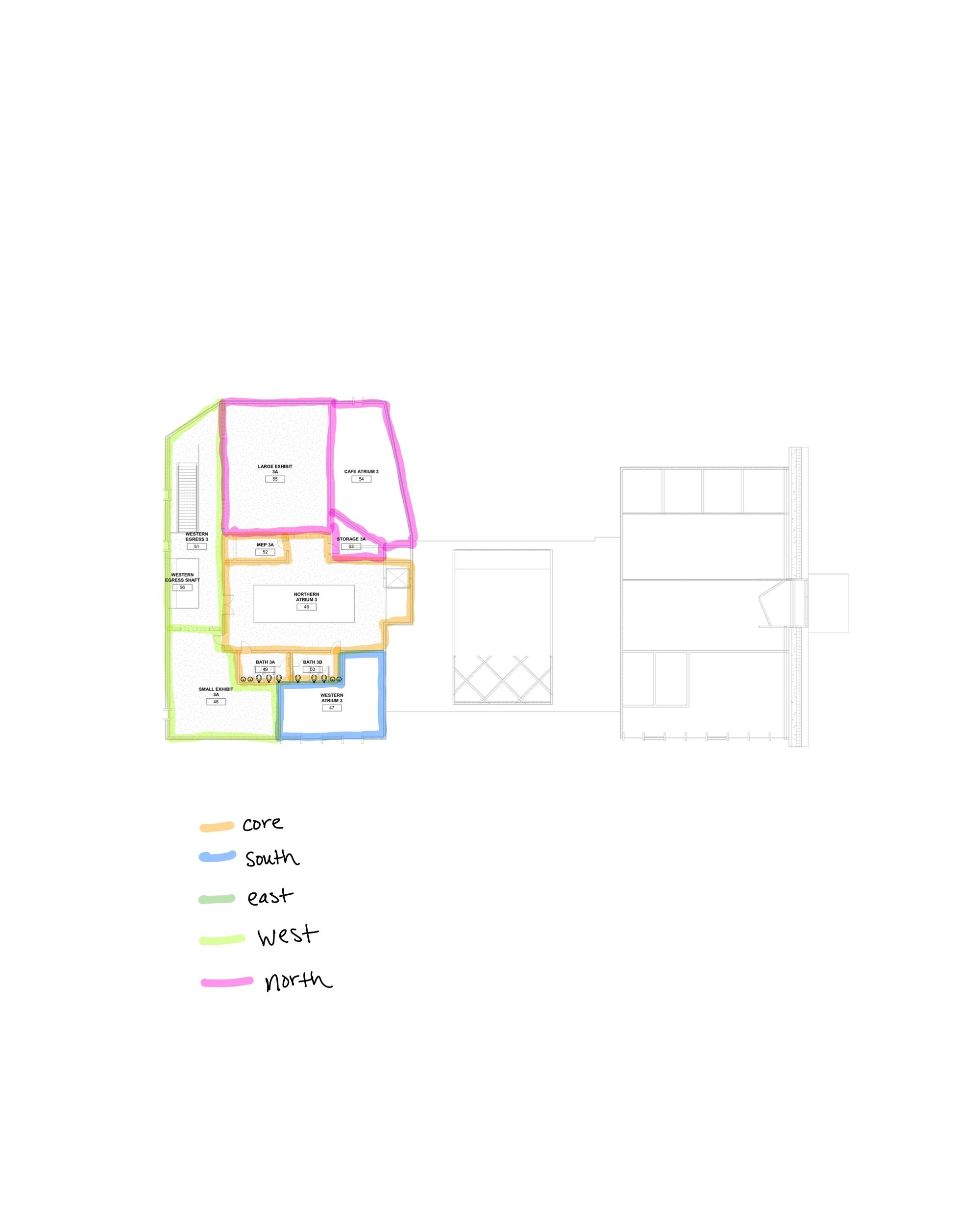
HVAC Zones:
Before modeling in Revit, I made annotated sketches of the floor plans to assess optimal zonal divisions to sort the various spaces in zones which would experience similar conditions in solar gain and wind flow. The zones were determined by proximity to a particular facade as well as the building wing in which the space is located.
L1
L2
L3
HVAC Model Overview:
- two MEP rooms with separate duct trees to facilitate the conditioning of the two wings
- Heat Pump located in each MEP room
- AHU on the roof
- Could not find a way to rapidly model radiant panels so I elected to represent them with default supply diffusers
- Return diffusers and ducts model to meet ventilation requirements
- Modeled supply and return ducts at the same height (12’6”) to reduce the amount of overhead space occupied by the HVAC system.
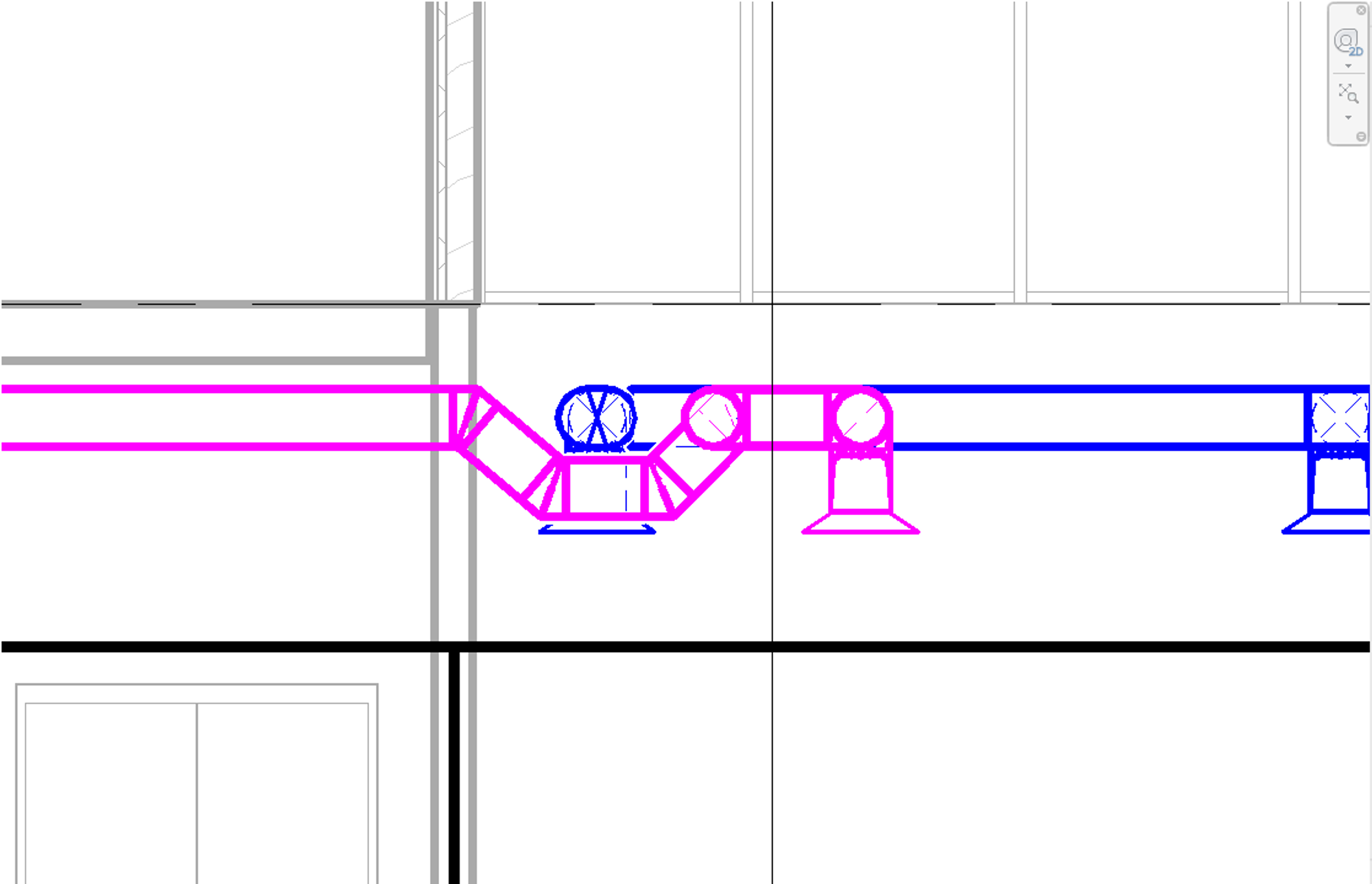
- Carefully designed duct networks to avoid path crossing between supply and return networks
- Moments of unavoidable crosses were addressed by modeling flexible duct reroutes in which the return ducts dipped below the supply ducts, while still remaining above the diffuser plane.
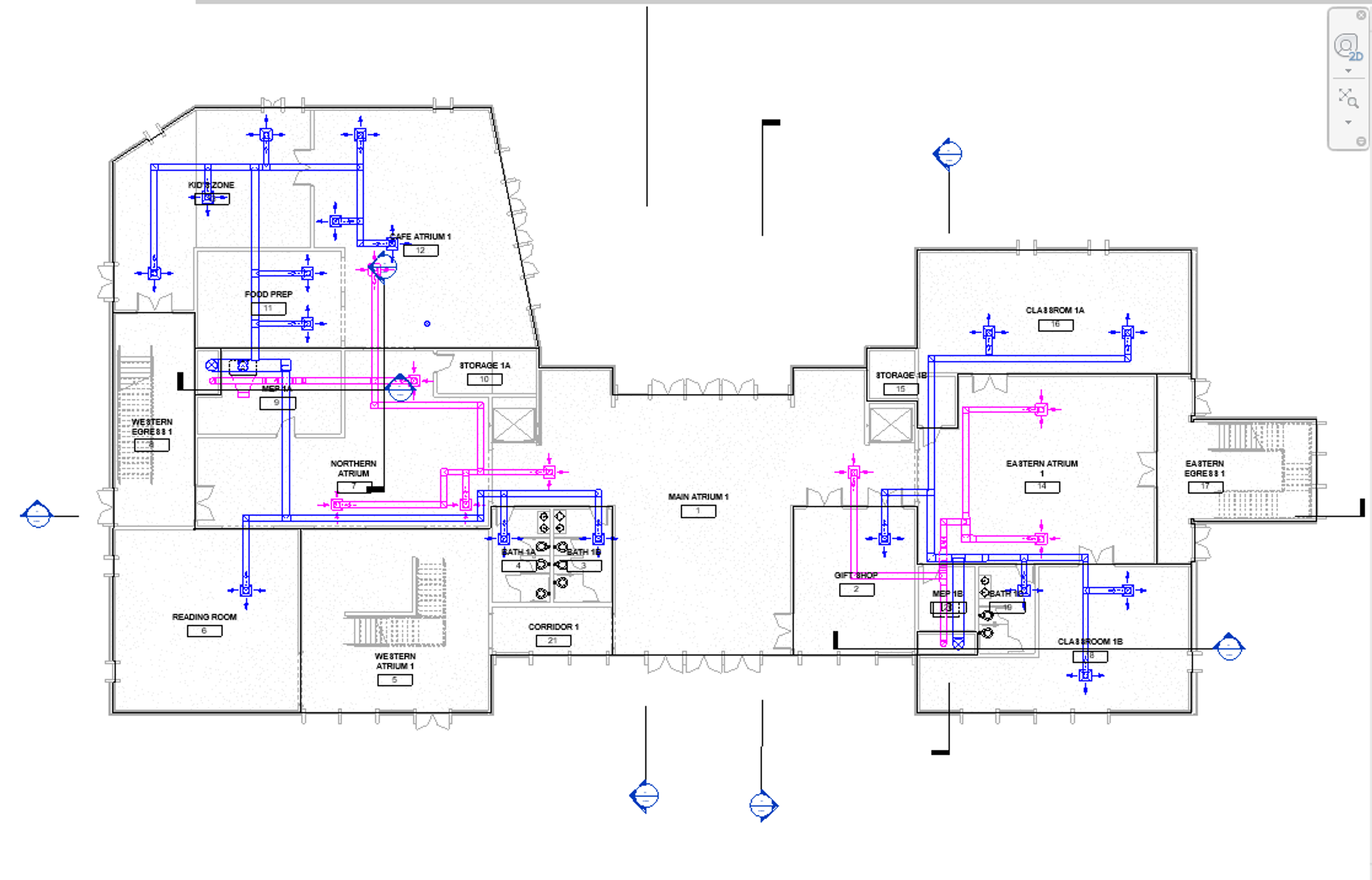
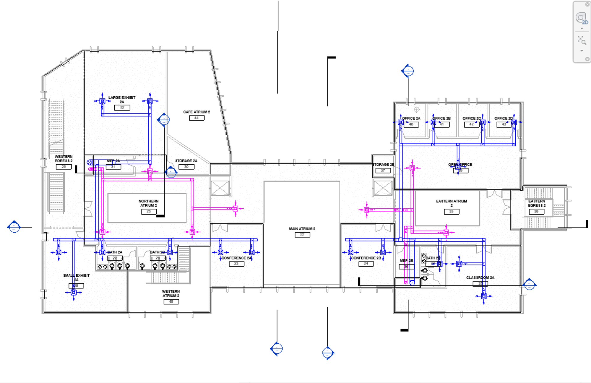
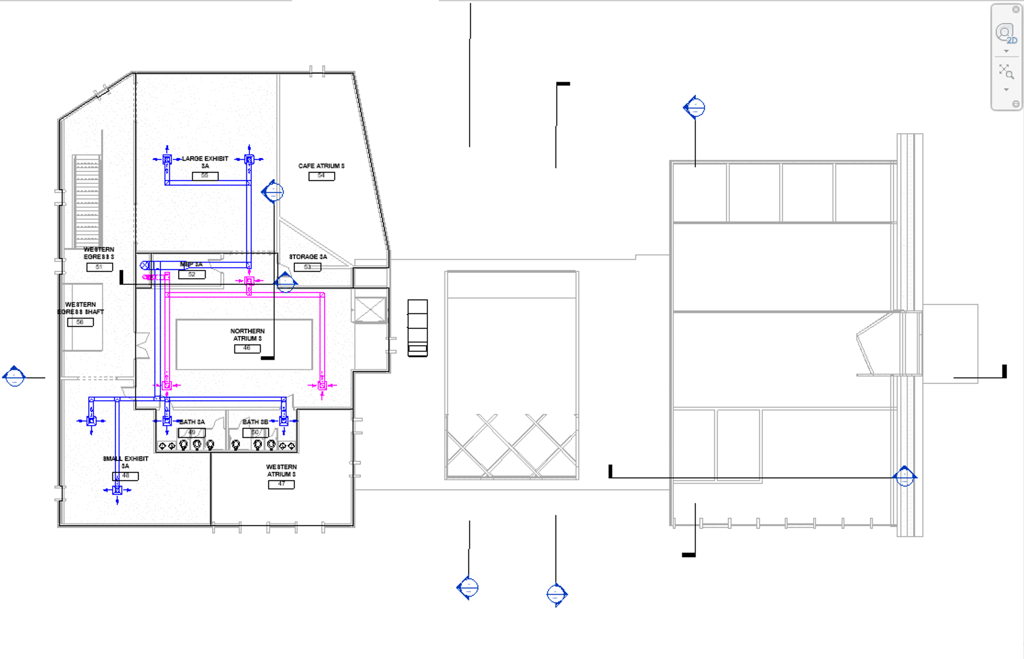
HVAC Duct Trees:
- supply and return diffuser height: 10ft
- Shaft ducts: 24”x24”
- Main supply ducts: 16”x12”
- Terminal supply ducts: 12”x12”
- Return ducts: 12x12”
L1
L2
L3
Load Simulations:
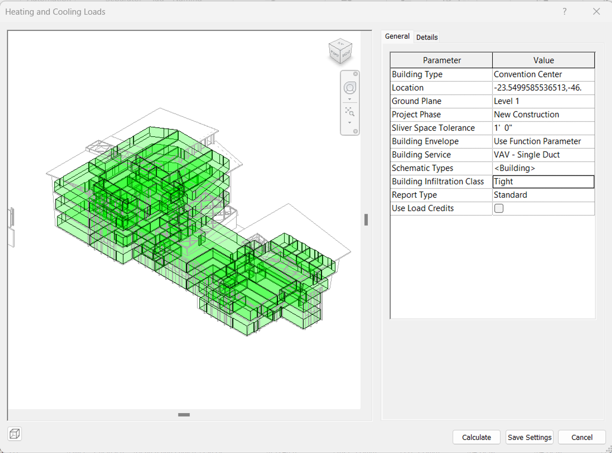
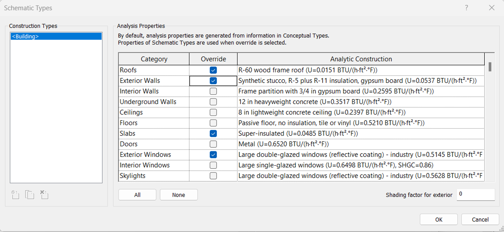
Simulation Results:
The room cfm values generated by the load simulation were used to determine the amount of diffusers required to meet ventilation requirements for each conditioned space. The results generated and the corresponding diffuser number calculations are in the pdf below:
More Views:
.png?id=3eee9207-e1c4-496d-a119-1c4835e095c5&table=block)
.png?id=edfaeed4-8406-4f96-8d33-851c8b7dee9c&table=block)