
Focus
The focus of this stage in your integrated design project is to explore how you can best implement the strategies that you identified for achieving your project goals as you design the features of your building’s structural system. For this check-in you’ll add these features to your building model:
- Grids
- Structural Framing Elements
- Structural Floors
- Beams & Beam Systems
- Structural Columns
- Structural Walls
- Foundations
Recommended Approach
At this point in our design process, we’ll continue adding the details to flesh out our initial building design ideas -- for this check-in, focusing on the materials, member sizes, and layout of the structural framing system.
Getting Started
Create a new Structural model and Link It to your Architectural model
Create a new Revit project
- Create a new Revit project for your structural model using the Structural Analysis project template.
- Save the new model as a Project to a folder on your local disk.
- Then, upload this new project to your ACC folder using the Collaborate tool in the Collaborate tab of the ribbon.
- Open the Collaborate > Collaborate tool choose the In The Cloud option to upload your model to your ACC project folder.
Link to your Architectural model
- Open the the Insert > Link Revit tool, and navigate to your Architectural model (the Cloud Revit architectural model in your ACC project folder).
Acquire the Coordinates from your linked Architectural model
- Switch to the default 3D view — so you can see an overview of your linked Architectural model.
- Open the Manage > Project Location > Acquire Coordinates tool.
- Select the linked architectural model to acquire the coordinate system from the Architectural model and apply it to your new Atructural model.
Copy/Monitor the Levels from your Architectural model
- Switch to the South elevation view.
- Open the Collaborate > Copy/Monitor tool > Select Link tool.
- Click on your building in the background to select your linked Architectural model.
- You’re now in Copy/Monitor mode, where you’ll select the elements to be copied from the linked model.
- Click the Copy tool in the ribbon.
- Select each of the Levels from the linked Architectural model — one at a time. Be sure to click all of the levels — Level 0 through the highest level. As you click on each of the levels in your Architectural model, equivalent levels will be created in your Structural model.
- Click the green Finish checkmark when done to close Copy/Monitor mode.
- Use the View > Plan Views > Floor Plan tool to create Floor Plan views corresponding to each of the levels in your Structural model.
Adjust the Project North direction in your Structural model
- If your project site does not align well with the cardinal compass directions, you should adjust the Project North direction in your Revit models to make your modeling and drafting tasks easier.
- To do this:
- Switch to the Level 1 floor plan view in your new Structural model.
- Zoom in on your Architectural model.
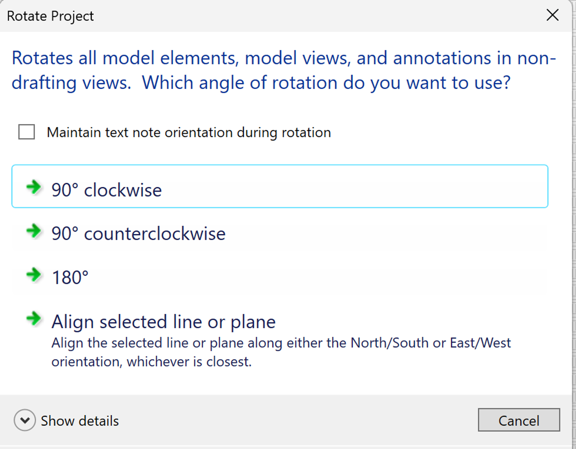
- Open the Manage > Project Location > Rotate Project North tool.
- Use the Align selected line or plane option, then click on the edge of one of the walls that run from the top to bottom of the drawing area to rotate the Revit elements in your model to better align with the drawing area and typical modeling tools snaps.
Copy/Monitor the Floors from your Architectural model
- Use the Copy/Monitoring tool to copy these elements from your architectural model:
- Floors -- to create matching structural floor elements in your structural model.
Start by Planning Your Structural Strategy
Before you dive into building modeling in Revit, start by carefully considering your overall structural system strategy:
- What structural material makes sense for the local conditions (availability and familiarity) as well as your project design goals -- for example, buildability (what material will be most cost- and time-effective) and sustainability (which has the best carbon footprint)?
- Would you like the structural system to be hidden from users of the building or an exciting design feature that’s part of the user experience?
- Should the structural framing be visible from the exterior? Visible on the interior? Or hidden in the walls and ceiling?
- Does your building form have an overall geometry or constraining elements (atriums, elevator shafts, stairs, etc.) that will help dictate the best grid layout?
- Will specific areas of your building benefit from different structural strategies? For example, can you use a very typical, closely-spaced column scheme in the office areas? Would a wide-open, few column, long span truss scheme work better for an atrium or exhibition space? Parts that don’t extend to the top-most level?
Create Grids in your Structural model
- Create Grids in your structural model to organize the placement of your structural framing elements.
- For steel, concrete, and heavy timber structures, Structural Columns are typically placed at Grid intersections.
- For light-frame wood structures, Grids are typically placed at the Core Face: Exterior of exterior walls and interior structural walls.
- With these Grids in place, you’re ready to start placing your structural framing elements.
Place Structural Framing Elements Precisely
- Use your Grids to align your structural framing elements:
- Structural Columns (centerlines or faces)
- Structural Walls
- Locate the tops of Beams and Beam Systems relative to the floors they support:
- Cast-in-place concrete beams are typically placed with their tops at the level of the floors they support.
- Steel beams are typically placed with their tops at the bottom of the floors they support. So, remember to lower them by the thickness of the floor assembly.
- Wood beams can go either way (it’s your design decision) -- embedded in the floor or placed below the floor.
What Size Should the Framing Elements Be?
With experience, you’ll develop an intuition for the approximate size of the framing elements based on the sizes you’ve seen in other buildings with similar conditions. So, as you get started, the member sizing is a bit of an educated guess. A good strategy is to make your initial sizes large enough to accommodate the largest potential size that the analysis might dictate. That way, resizing the elements to make them smaller where possible will be less impactful.
Does the Structural System affect Other Systems?
The design of your structural system will have a big effect on the design work that will be required for HVAC systems in an upcoming module. The layout and depth of the beams and beam systems often dictate the space and paths available for routing ductwork for your HVAC system.
Typically -- the longer the spans, the deeper the beams. And the deeper the beams, the tighter the space available for ductwork in the ceiling.
How Detailed Should This Version of Model Be?
At this stage, you’ll want your structural model to accurately reflect the locations of the major framing elements and essential components of your structural strategy -- the beams and beam systems, the structural walls, any trusses or long-span elements.
For the scope of this course and design project, you won’t be able to resolve all the framing details to handle every case throughout your building’s geometry -- and that’s okay! Our goal is to understand the big structural design decisions and their impact on other building systems. There will be lots of unknowns and issues for future resolution -- that’s typical, expected and okay!
Thinking Ahead
In the weeks ahead, we’ll continue to develop the details of this initial building model as you design each of the major building systems. If it helps your creative process, you can start thinking ahead to:
HVAC Systems (Module 9)
- Designing the heating, cooling, and ventilation systems to provide the fresh air required and handle the heating and cooling loads predicted for your building.
- Where can you use passive heating or cooling through the building envelope?
- Where will active heating and cooling systems be required?
- How will your Structural System choices and framing member sizes affect your options for placing the HVAC System elements?
Progress Check-In / Documenting Your Design Journey
About Design Journal Entries
You’ll be sharing your ongoing design process and progress with others in our class community through a posting in an online Design Journal using Notion.
Feel free to use whatever format best captures the ideas that you want to share -- text, images, sketches, photos of hand sketches, intermediate models, results of analyses, and so on.
For this class, your design process is as important as the final result.
Post a Design Journal Entry
Create a new posting sharing your Design Journal entry on this linked Notion page:
Your Design Journal entries this week should highlight your design thinking that influenced your decisions about:
- your overall strategy and the features of the structural system
- the material and framing system selected
- the locations of structural columns and major framing elements
- any special structural challenges
Model Coordination
Upload the latest versions of your architectural and structural models to Autodesk Construction Cloud, then copy these latest versions into your Model Coordination space to explore the integrated design.
- Walk through a merged model view to experience how the architectural and structural designs work together.
- Look for any potential conflicts or issues that require resolution.
Weekly Design Project Check-In
Meet with a member of the teaching team to review your progress and share tips about how to proceed.