
Focus
The focus of this stage in your integrated design project is to explore how you can best implement the strategies that you identified for achieving your project goals as you design the features of your building’s HVAC system. For this check-in you’ll add these features to your building model:
- HVAC Analysis Features
- Spaces
- HVAC Zones
- HVAC System Elements
- Air-Based System Components
- Ducts
- Air Terminals
- Ducts
- Zone Controllers
- Air Handlers
- Fluid-Based System Components
- Piping
- Radiators
Recommended Approach
At this point in our design process, we’ll continue adding the details to flesh out our initial building design ideas -- for this check-in, focusing on your overall heating, ventilating, and cooling strategy and the HVAC system elements that will illustrate your proposed systems.
Step 1: Start with an Overall HVAC Strategy
Before you dive into building modeling in Revit, start by carefully considering your overall HVAC system strategy:
- What is the magnitude of the ventilating, heating, and cooling loads that your HVAC system design will need to provide? These will be based on a combination of:
- Your project location, climate, and solar exposure (external loads)
- Your space types and number of people occupying each space (internal loads)
- The thermal properties (thermal resistance, thermal mass, etc.) assigned to all of your building envelope elements.
- For your project location, do you have more of a heating problem (need to warm the spaces to keep them comfortable) or a cooling problem (need to cool the spaces)? Or is it evenly split?
- You’ll need to provide adequate ventilation to meet the minimum fresh air levels required by your buildings occupants. You may be able to use natural ventilation throughout much of the year (when the outside air is thermally comfortable), but there will typicaly be some times during the year where ventilation will need to be supplied mechanically by your HVAC system.
- You can compute the amount of fresh air that will be required in each space based on its use and the number of occupants.
- In many project locations, you’ll need to supplement the heat available from the sun (in your passive design of the building envelope) with some sort of active heating system.
- What type of heating systems can you use?
- Can you capture solar heat from your passive design features (glazing and shading) to meet part of your heating requirements during the warming months -- but provide shading to prevent excess unwanted heat gain during the cooling months?
- What type of heating can you use to supplement the heating needs when required?
- Warm air delivered thru ducts or an underfloor distribution system?
- Radiant heating delivered thru fluid piping that runs through the floor or baseboard radiators?
- Electric resistive heating?
- In most non-residential buildings, keeping the spaces cool enough is actually a bigger challenge than heating them. While we can design our building envelopes to keep unwanted heat out, the heat generated by the building occupants (the internal loads) often determines the cooling that must be provided.
- What type of cooling systems can you use?
- Can you shield your building from the solar heat using your passive design features (shading) to reduce the cooling load during the cooling months?
- Can you use natural ventilation, air movement, or water features (evaporation) to provide some of the cooling naturally?
- What type of cooling can you use to supplement the cooling needs when required?
- Cool air delivered thru ducts or an underfloor distribution system?
- Fluid-based cooling? For example to heat pump units or chilled beams in the spaces needing cooling?
- Individual AC units is specific spaces?
Step 2: Create a Linked Mechanical Model
Step 2.1 - Create a new Revit project
- Create a new Revit project for your structural model using the Systems project template.
- Save the new model as a Project to a folder on your local disk.
- Then, upload this new project to your ACC folder using the Collaborate tool in the Collaborate tab of the ribbon.
- Open the Collaborate > Collaborate tool choose the In The Cloud option to upload your model to your ACC project folder.
Step 2.2 - Link to your Architectural model
- Open the the Insert > Link Revit tool, and navigate to your Architectural model (the Cloud Revit architectural model in your ACC project folder).
- Switch to a 3D View and select the linked Architectural model.
- Edit the Type properties of the linked Architectural model, and turn on the checkbox Room Bounding property. This is ESSENTIAL — you’ll use the building elements in your Architectural model to define your HVAC spaces in your Mechanical model.
Step 2.3 - Acquire the Coordinates from your linked Architectural model
- Switch to the default 3D view — so you can see an overview of your linked Architectural model.
- Open the Manage > Project Location > Acquire Coordinates tool.
- Select the linked architectural model to acquire the coordinate system from the Architectural model and apply it to your new Atructural model.
Step 2.4 - Copy/Monitor the Levels from your Architectural model
- Switch to the South elevation view.
- Open the Collaborate > Copy/Monitor tool > Select Link tool.
- Click on your building in the background to select your linked Architectural model.
- You’re now in Copy/Monitor mode, where you’ll select the elements to be copied from the linked model.
- Click the Copy tool in the ribbon.
- Select each of the Levels from the linked Architectural model — one at a time. Be sure to click all of the levels — Level 0 through the highest level. As you click on each of the levels in your Architectural model, equivalent levels will be created in your Structural model.
- Click the green Finish checkmark when done to close Copy/Monitor mode.
- Use the View > Plan Views > Floor Plan tool to create Floor Plan views corresponding to each of the levels in your Mechanical model.
Step 2.5 - Adjust the Project North direction in your Mechanical model
- If your project site does not align well with the cardinal compass directions, you should adjust the Project North direction in your Revit models to make your modeling and drafting tasks easier.
- To do this:
- Switch to the Level 1 floor plan view in your new Structural model.
- Zoom in on your Architectural model.
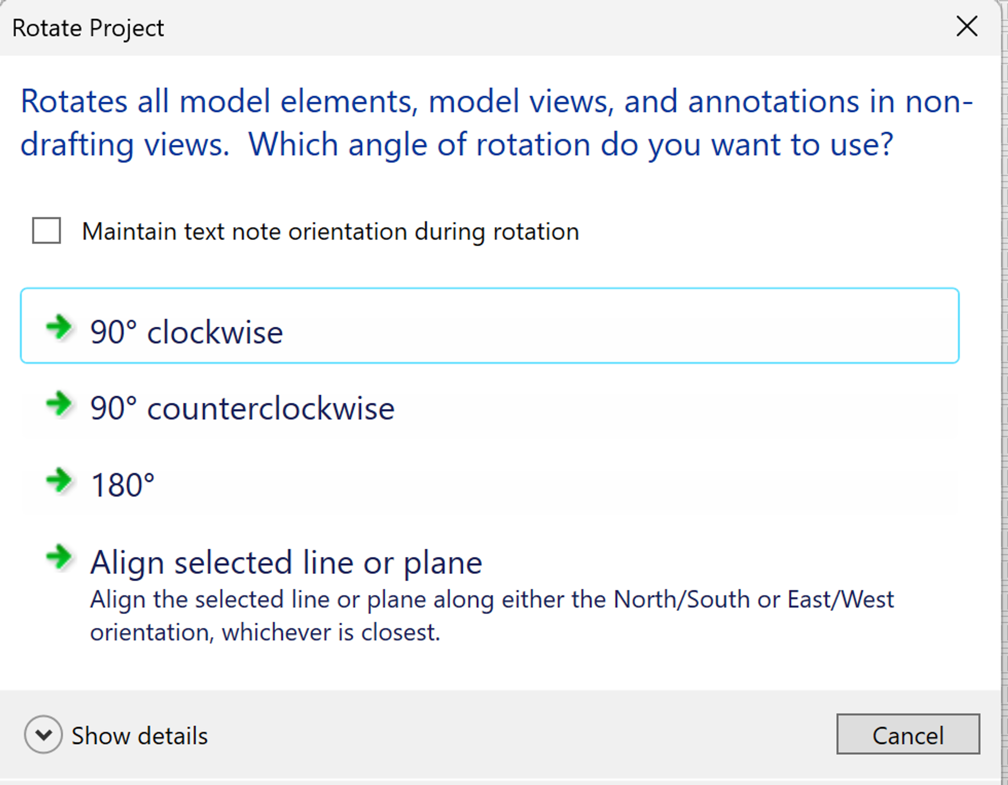
- Open the Manage > Project Location > Rotate Project North tool.
- Use the Align selected line or plane option, then click on the edge of one of the walls that run from the top to bottom of the drawing area to rotate the Revit elements in your model to better align with the drawing area and typical modeling tools snaps.
Step 3: Calculate the Heating and Cooling Loads
Before you get started placing HVAC system elements, you’ll need to:
- Place Spaces and HVAC Zones in your HVAC model to specify the way your building spaces will be used and thermally zoned.
- Calculate the heating and cooling loads in each of your spaces. Run the Heating and Cooling Loads report in Revit to compute the supply air volume required for:
- Ventilation (all regularly occupied spaces require this). This is the minimum supply air volume that must be provided for occupant well-being at times when natural ventilation cannot be used. This volume is typically the smallest of the three.
- Heating (for any air-based portion of your heating system). This is the supply air volume that must be provided to deliver the required warm air to your spaces (as a supplement to heat provided by other sources — for example, radiant floor heating or radiators).
- Cooling (for any air-based cooling system). This is the supply air volume that must be provided to deliver the required cool air to your spaces (as a supplement to cooling provided by other sources). This volume is often the largest of the three due to the heat generated by the lighting and building occupants (internal gains).
Step 4: Model the HVAC System Elements
- Air Terminals in each of the spaces to provide ventilation, heating, and cooling air. The volume provided by the air terminals should meet or exceed the maximum of the three requirements.
- Supply Ducts connecting your supply air terminals back to your mechanical room. Keep the number of terminals supplied by each branch of your duct system small and balanced.
- As you place your ducts, try to create them with the approximate size that will be needed to handle the air flowing through them — determined by the cumulative volume of the downstream air terminals being supplied.
- Use this table as a guide:
- Run your supply ducts back to your mechanical room spaces, but DO NOT attempt to connect them to an air handler.
- Return Ducts are optional.
- You can provide return air terminals and ducts in spaces where controlling the return air is critical.
- But many buildings use a loose approach where return air is drawn back through a few centrally located return air terminals in the hallways or open spaces.
- Duct Sizing using Revit’s Duct Sizing tool is optional.
- Using the Duct Sizing tool can be very challenging, because it requires that you air terminals and duct connections be modeled and connected accurately to work properly.
- So, if you do use the Duct Sizing tool, be sure to test small branches of your duct systems independently (for example, 3 or 4 air terminals at a time) to make debugging easier.
- Zone Controllers are optional.
- if your design includes zone controllers (for example, VAV units) to control (and heat or cool) the airflow for specific zones (groups of air terminals), place these VAV units and connect your ducts to them.
- Air Handlers should be included.
- Place air handler components in your HVAC model to indicate where they will be located:
- Central units on the roof or in the basement.
- Or multiple, decentralized units in your mechanical rooms on each level.
- DO NOT attempt to connect your ducts to the air handler units. Connecting your ducts to these air handler units can be a VERY time consuming and TEDIOUS process. It’s certainly possible, but it’s beyond the scope of what we’re asking for in this assignment.
Total Volume
of Downstream Air
Being Supplied | Required
Cross-Section Area | Potential
Rectangular Duct
Cross-Sections |
6000 CFM | 6 SF | 24x36
18x48
12x72 |
4000 CFM | 4 SF | 24x24
18x32
12x48 |
3000 CFM | 3 SF | 18x24
12x36 |
2000 CFM | 2 SF | 18x16
12x24 |
1000 CFM | 1 SF | 12x12
9x16 |
500 CFM | 0.5 SF | 9x9 |
- Radiant Floors — place piping in the floor slabs of each of your spaces to specify where the radiant heating pipes will be located. Run the radiant heating piping loops back to your mechanical room spaces, where the individual pipe runs would be joined in a valve manifold. But DO NOT attempt to connect all the pipes to a valve manifold.
- Radiators — place radiator components on the walls of spaces that will be heated this way. Then, connect the radiators with piping that loops back to your mechanical room spaces. DO NOT attempt to connect all the pipes to a valve manifold.
How Detailed Should This Version of Model Be?
Our goal in modeling the HVAC system is to understand the impacts of your design decisions and find ways to improve your design -- NOT to create a perfect Revit model.
At this stage, you’ll want your mechanical model to accurately reflect the locations of the major elements and essential components of your HVAC strategy. But to keep this assignment from becoming overwhelming, you should:
- Keep your system modeling very high level.
- Get the main components in your HVAC strategy modeled to illustrate how they’ll work together with the other building systems...
- Learn to let go of the small details when you’re in this design exploration phase. The details will get resolved later in the process.
It’s very easy to get lost in all the detail of modeling the HVAC system components -- for example, getting all the ducts to connect properly can be very tricky, especially if they get very large when you resize them to match the airflow required. So:
- DO NOT… I repeat, DO NOT… I repeat again, DO NOT agonize over the duct connections that just don’t want to connect as desired.
- For the scope of this course and design project, you won’t be able to resolve all the HVAC details -- and that’s okay! There will be lots of unknowns and issues for future resolution -- that’s typical, expected and okay!
What Size Should the HVAC System Elements Be?
Similar to our challenge when doing the structural design, the answer is -- we don’t know yet!
In practice, we can compute the overall and cooling loads for the overall building (or for each zone in the building) and use this information to pick appropriately-sized heating and cooling equipment. But, selecting that equipment is beyond the scope of this course -- so, you can place some moderately-sized mechanical equipment as placeholders (to be sized by an HVAC engineer later).
Duct sizing is something that we can do now based on the supply air requirements that you’ve computed for each space. As you get started modeling, place ducts using an approximate size -- say 12x12 or 12x16 -- as placeholders. Then, you can use the Duct Sizing tool to compute the actual sizes based on the airflow demands of the terminal that you connect to each duct.
Does the HVAC System affect Other Systems?
The design of your envelope system, your structural system, and your HVAC system all have to work together:
- Your envelope system choices have a huge impact on the heating and cooling loads that your building will experience. So, careful envelope design can be used to greatly reduce the size of the components in your HVAC system.
- Your structural system choices have a big impact on the space available for placing ducts as part of your air-based HVAC systems. The layout and depth of the beams and beam systems often dictate the space and paths available for routing ductwork.
Progress Check-In / Documenting Your Design Journey
About Design Journal Entries
You’ll be sharing your ongoing design process and progress with others in our class community through a posting in an online Design Journal using Notion.
Feel free to use whatever format best captures the ideas that you want to share -- text, images, sketches, photos of hand sketches, intermediate models, results of analyses, and so on.
For this class, your design process is as important as the final result.
Post a Design Journal Entry
Create a new posting sharing your Design Journal entry on this linked Notion page:
Your Design Journal entries this week should highlight your design thinking and analysis results that influenced your decisions about:
- your overall HVAC system strategy
- your heating strategy and how you implemented it in your design
- your cooling strategy and how you implemented it
- any special HVAC system challenges that you encountered
Model Coordination
Upload the latest versions of your architectural, structural, and HVAC models to Autodesk Construction Cloud, then copy these latest versions into your Model Coordination space to explore the integrated design.
- Walk through a merged model view to experience how the architectural, structural, and HVAC designs work together.
- Look for any potential conflicts or issues that require resolution.
Weekly Design Project Check-In
You’ll meet with a member of the teaching team to review your progress and share tips about how to proceed.