Copy/Monitor Room Bounding Floors from the Linked Architectural Model
Copy Monitor the Floor Elements from the Architectural model
Set the Type Properties for the Architectural model to be Room Bounding
Example 1: Using Daylight Only
‣
Run a New Illuminance Analysis with the Default Settings (Daylight Only)
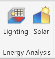
Analyze > Energy Analysis > Lighting
The default settings include Override Lighting > Scheme turned on (checked), and these settings perform the analysis using daylight only.
Before each run, Revit sets the scheme in the “_Lighting Analysis Model View” to “Interior: Sun only.”
Your light fixtures are ignored, and the results show only how much daylight reaches each surface.
That’s the right choice for daylighting studies and LEED daylight credits (LEED 2009 IEQc8 opt1, LEED v4 EQc7 opt2), which are meant to measure sunlight alone.
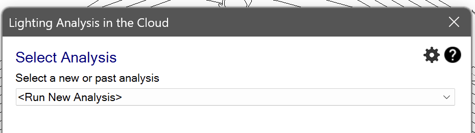
<Run New Analysis>
Choose Analysis = Illuminance Analysis
Start the analysis and wait for the results
‣
View the Illuminance Analysis Results for Daylight Only
Open the Coordination > ??? > 3D Views > _InsightLighting Model View in the Project Browser.
If you used the default Lighting Analysis Settings (Daylight Only), the Rendering Settings for this view will be ignored.
Use the Section Box to view results in a 3D view
Example 2: Using Artificial Lights
‣
Run Another Illuminance Analysis Incorporating Artificial Lights from Rendering Settings
Adjust the Lighting Settings used in the analysis
In the “_Lighting Analysis Model View,” open Rendering Settings and set the Lighting Scheme:
“Interior: Sun and Artificial” combines daylight with your fixtures.
“Interior: Artificial only” shows the fixtures without daylight, like a night-time check.
Under Artificial Lights, set each fixture’s Dimming to 1 (on) or 0 (off).
Analyze > Energy Analysis > Lighting
Click the Gear Icon to Adjust Lighting Analysis Settings
UNCHECK Override "Lighting > Scheme"
Turned off (unchecked) lets the view’s own Rendering Settings take effect, which is how you add electric lighting:
This gives a much more realistic picture of interior light levels. It also means the results no longer represent daylight alone, so don’t use a run like this for a daylight-only credit.
<Run New Analysis>
Choose Analysis = Illuminance Analysis
Choose Levels = Selected levels
Start Analysis and wait for the results
When the analysis is complete, return to the Lighting Analysis Tool
Select an existing analysis
Accept and Save results
‣
View the Illuminance Analysis Results for Your Artificial Lights
Open the Coordination > ??? > 3D Views > _InsightLighting Model View in the Project Browser.
If you modified the Lighting Analysis Settings to include artificial lights, the Rendering Settings for this view determine the illumination values displayed.