Workflow
Creating a Power Circuit
- Select a Receptacle in a Power Plan view or 3D view.
- Open Modify | Electrical Fixtures > Create Systems > Power
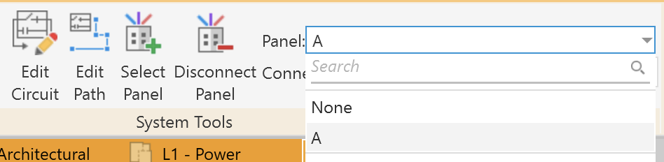
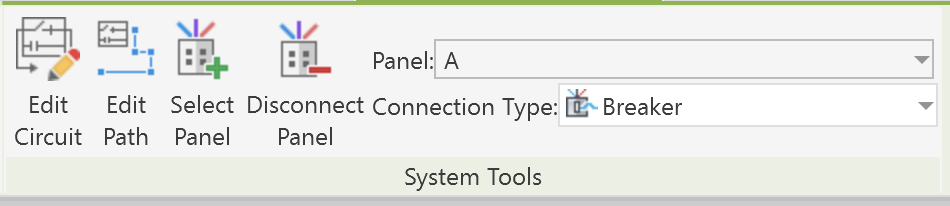
- Select the Panel for this power circuit.
- Choose a Panel from the drop-down menu of available panels (already placed in this project) in the System Tools section of the Ribbon.
- Choose the devices to be included in this power circuit.
- Open the Edit Circuit tool.
- Add the devices to this power circuit.
- Click Add to Circuit.
- Select the additional receptacles and devices to be added.
- Note: Circuit requirements
- Click Finish Editing Circuit when done.

Viewing a Power Circuit
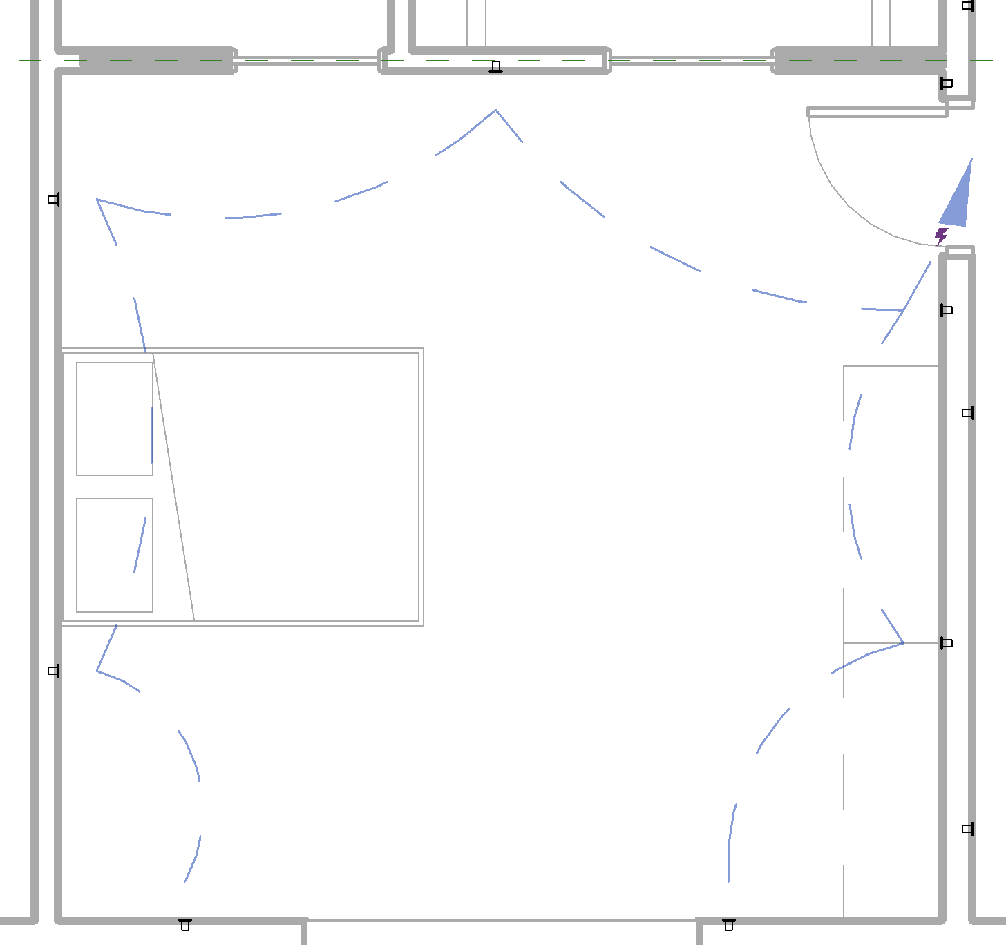
- Hover over a receptacle in the power circuit and press Tab once.
- Lines will display the receptacles included in the circuit.
- Click once to select and modify the circuit.
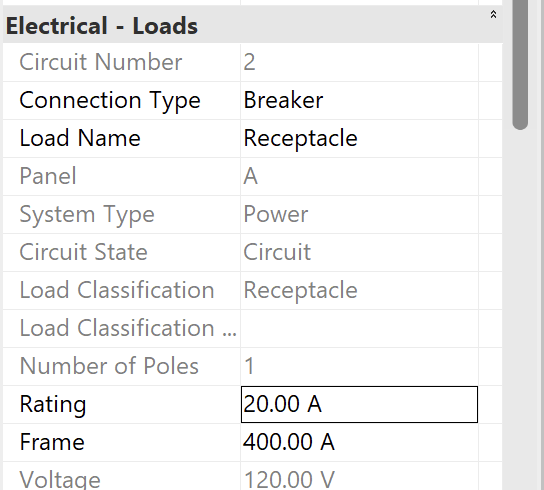
- The Properties Palette displays information about the Electrical Loads on the circuit (based on the receptacles and devices included):
- Connection Type
- Load Name
- Rating (Breaker Size required)
- Voltage
- Apparent Current
- Assuming 1.5 A per receptacle
Converting the Temporary Circuit Lines to Wire
- Hover over a receptacle in the power circuit and press Tab once.
- Lines will display the receptacles included in the circuit.
- Click once to select and modify the circuit.
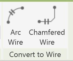
- Choose the wire style to use from the Convert to Wire section of the ribbon.
AI Prompts
You can download this model file here:

Adding Power Circuits
Prompt | Tool Options
🟢 = Autodesk Asst
🔵 = Revit MCP
🟣 = Python + Dynamo |
Add power circuits to this residential unit:
• Create separate power circuits for each room or use to meet all code requirements.
• Connect all circuits to the electrical panel at the entry.
• Convert all temporary wires to Arc Wires.
• Show short 3’ home-run wires from the last devices on each circuit aimed at the panel.
As you work, send me a message after each step saying what you did and what you found. | 🟣 |
Tag the circuits with their Load Names | 🟣 |
Claude Response
I'll start by checking the open Revit model to find the panel, rooms, and temporary wires before building any circuits.
Now I'll inventory the electrical content: panel, devices, existing circuits and wires.
Revit 2024+ uses .Value instead of .IntegerValue; adjusting.
Step 1 – Model inventory done. Model "261109 Sample Apartment Electrical System" is open, one level of rooms on L1: Closet, Bath, Bedroom, Living, Kitchen, Entry.
What I found:
- Panel A (208V MLO lighting & appliance panelboard) sits in the Entry.
- 26 receptacles: 8 Bedroom, 7 Living, 1 Entry, 1 GFCI in Bath, 4 GFCI in Kitchen, 2 weatherproof GFCI outside (no room). Plus a Dishwasher with a power connector.
- Existing circuits: A-1 (Entry receptacle) and A-2 (7 of the 8 Bedroom receptacles — one was missed). Everything else is uncircuited.
- No wires exist yet — every circuit is only showing as temporary wiring, so the Arc Wire conversion will cover all of them.
- Can't circuit: the Refrigerator and Cooktop families have no electrical connector, so they can't join a circuit as-is. Closet has no devices.
Next: checking panel settings and the electrical plan view, then building the circuits.
Step 2 – Panel and view check done. Panel A is 225 A MLO, 120/208 V 3-phase wye, 42 spaces, 20 A breakers on the two existing circuits. Its own upstream feed is unconnected (normal for a unit panel with no service modeled). Wiring will go in the L1 - Power plan.
Circuit plan, based on NEC 2023 dwelling requirements:
- A-1 Entry – keep as is
- A-2 Bedroom – keep, add the missed receptacle (AFCI)
- Living – new 20 A (AFCI)
- Kitchen countertop – two new 20 A small-appliance circuits, GFCI (210.11(C)(1))
- Dishwasher – new dedicated circuit, GFCI (210.8(D))
- Bath – new dedicated 20 A, GFCI (210.11(C)(3))
- Exterior – new 20 A for the two weatherproof GFCI receptacles
Building these now.
Step 3 – Circuits created. Panel A now has 8 single-pole 20 A, 120 V circuits:
Ckt | Load | Devices |
A-1 | Entry Receptacle | 1 |
A-2 | Bedroom Receptacles | 8 (added the missed one) |
A-3 | Living Receptacles | 7 |
A-4 | Kitchen Countertop SABC 1 | 2 GFCI |
A-5 | Kitchen Countertop SABC 2 | 2 GFCI |
A-6 | Dishwasher (dedicated, 500 VA) | 1 |
A-7 | Bath Receptacle (dedicated) | 1 GFCI |
A-8 | Exterior Receptacles | 2 WR GFCI |
All 24 connectable devices are on a circuit; Bedroom and Living are each under the 13-outlet limit for a 20 A circuit. Next: converting the temporary wiring to Arc Wires in L1 - Power.
Verifying the wires and looking at the plan.
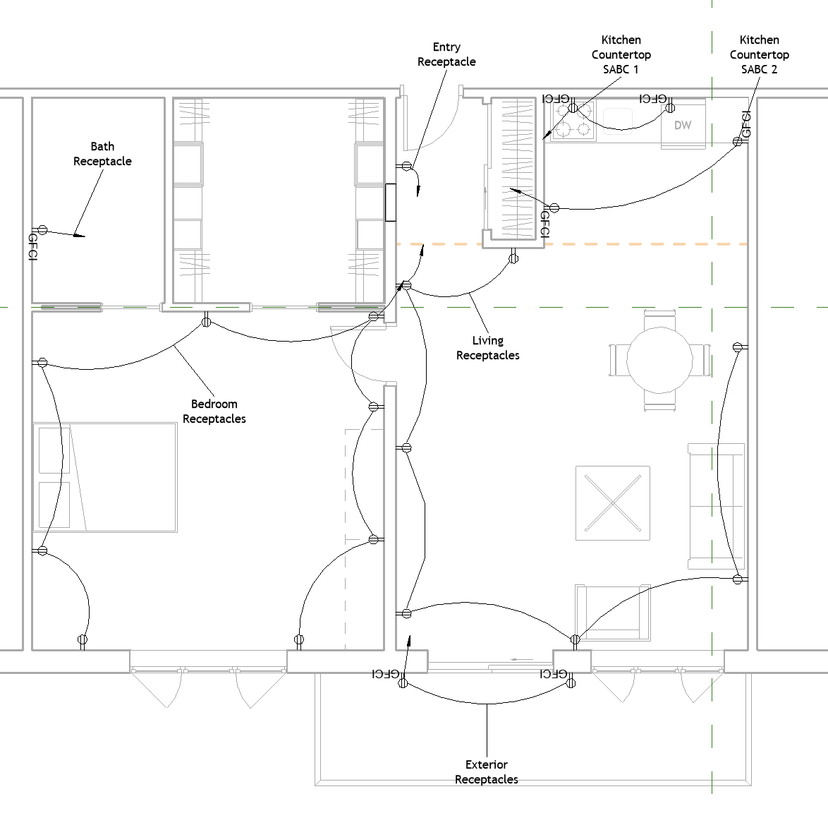
Step 4 – Arc Wires done and model saved. Created 24 THWN Arc Wires in L1 - Power: each circuit is daisy-chained device to device, ending in a home run toward Panel A in the Entry. Every receptacle and the dishwasher is now wired, no devices are left on temporary wiring, and the model has 0 warnings.
Panel A in the Entry now feeds eight 20 A power circuits, A-1 through A-8, one per room or use, all drawn as Arc Wires in L1 - Power. I saved the model.
A few things you should handle before issue:
- Refrigerator and cooktop aren't circuited. Their families have no electrical connector. If they're electric, swap in families that have connectors. The cooktop then needs a dedicated 2-pole 208 V circuit. A dedicated refrigerator circuit is also good practice.
- No laundry circuit. NEC 210.11(C)(2) requires one, but there's no laundry space in this model. If the unit has one, add it.
- AFCI/GFCI protection isn't recorded in the model. Mark these on the panel schedule or in circuit notes:
- AFCI for Bedroom, Living and Entry
- GFCI for Kitchen countertop, Dishwasher, Bath and Exterior
- Wire paths are auto-generated. The arcs chain each device to its nearest neighbour and end with a home-run arrow near the panel. Some routes cross walls or overlap near the panel, so you may want to tidy them for presentation.
- Panel A has no upstream feed. That's fine if the service isn't modelled yet.