Workflow - Creating a Power Circuit for the Lighting
Creating a Power Circuit
- Select a Lighting Fixture in a Power Plan, Lighting Plan, or 3D view.
- Open Modify | Lighting Fixtures > Create Systems > Power
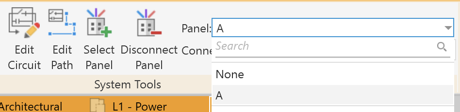
- Select the Panel for this power circuit.
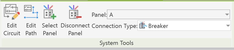
- Choose a Panel from the drop-down menu of available panels (already placed in this project) in the System Tools section of the Ribbon.
- Choose the devices to be included in this power circuit.
- Open the Edit Circuit tool.
- Add the devices to this power circuit.
- Click Add to Circuit.
- Select the additional lighting fixtures to be included in this circuit.
- Click Finish Editing Circuit when done.

Viewing a Power Circuit
- Hover over a lighting fixture in the power circuit and press Tab once.
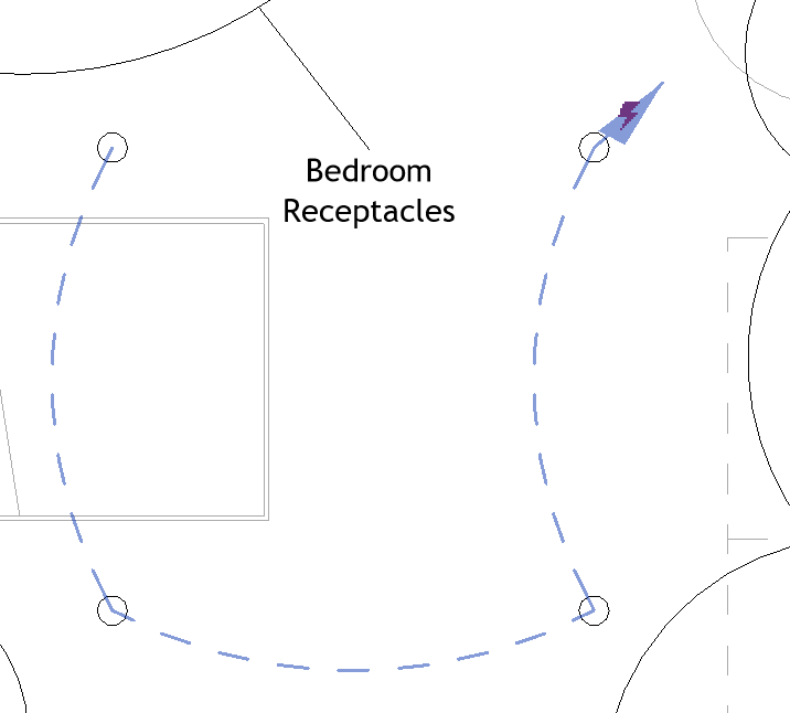
- Lines will display the lighitng fixtures included in the circuit.
- Click once to select and modify the circuit.
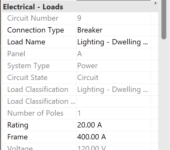
- The Properties Palette displays information about the Electrical Loads on the circuit (based on the receptacles and devices included):
- Connection Type
- Load Name
- Rating (Breaker Size required)
- Voltage
- Apparent Current
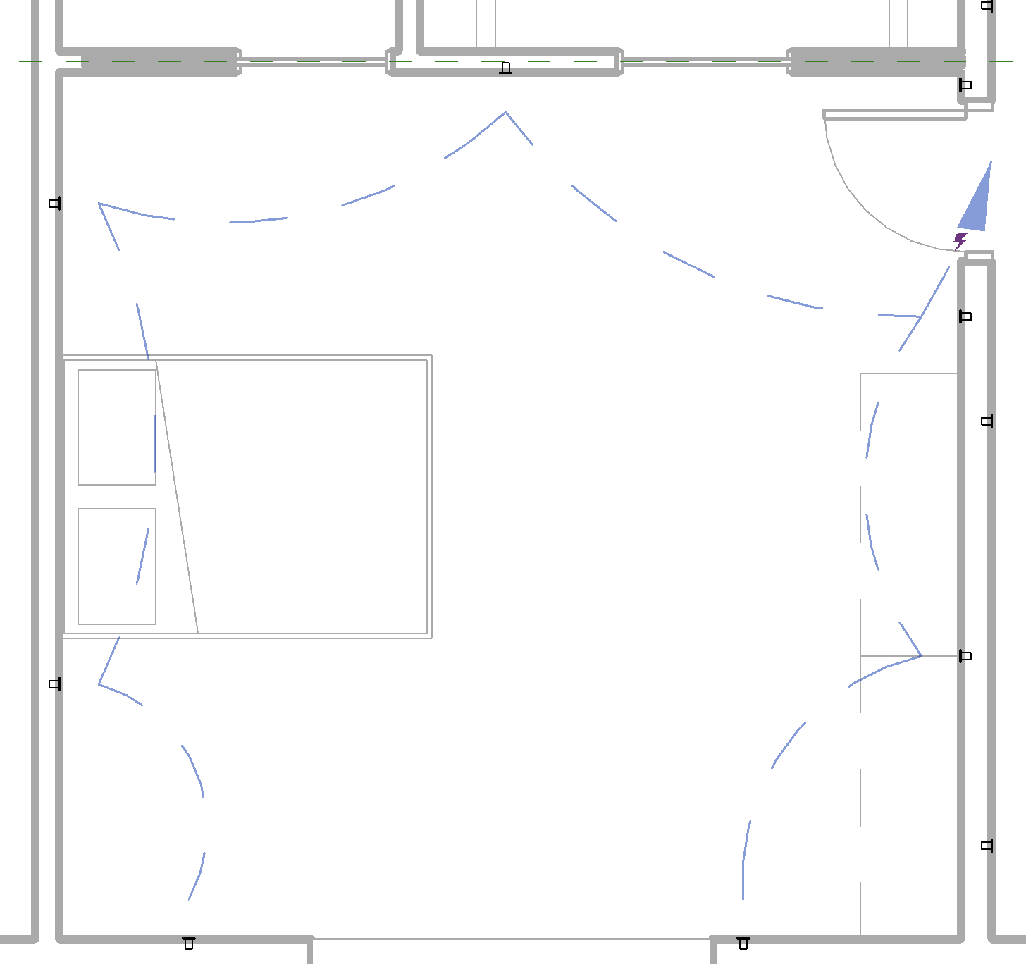
Converting the Temporary Circuit Lines to Wire
- Hover over a lighting fixture in the power circuit and press Tab once.
- Lines will display the receptacles included in the circuit.
- Click once to select and modify the circuit.
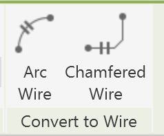
- Choose the wire style to use from the Convert to Wire section of the ribbon.
Workflow - Creating a Switch System for the Lighting
Creating a Switch System
- Select a Lighting Fixture in a Power Plan, Lighting Plan, or 3D view.
- Open Modify | Lighting Fixtures > Create Systems > Switch
- Open Switch Systems > Select Switch
- Choose the switches to be included in this switch circuit.
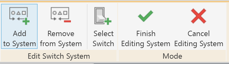
- Open the Edit Switch System tool.
- Click Add to System to add switches to the circuit.
- Select the switches to be included in this circuit.
- Click Finish Editing System when done.
AI Prompts
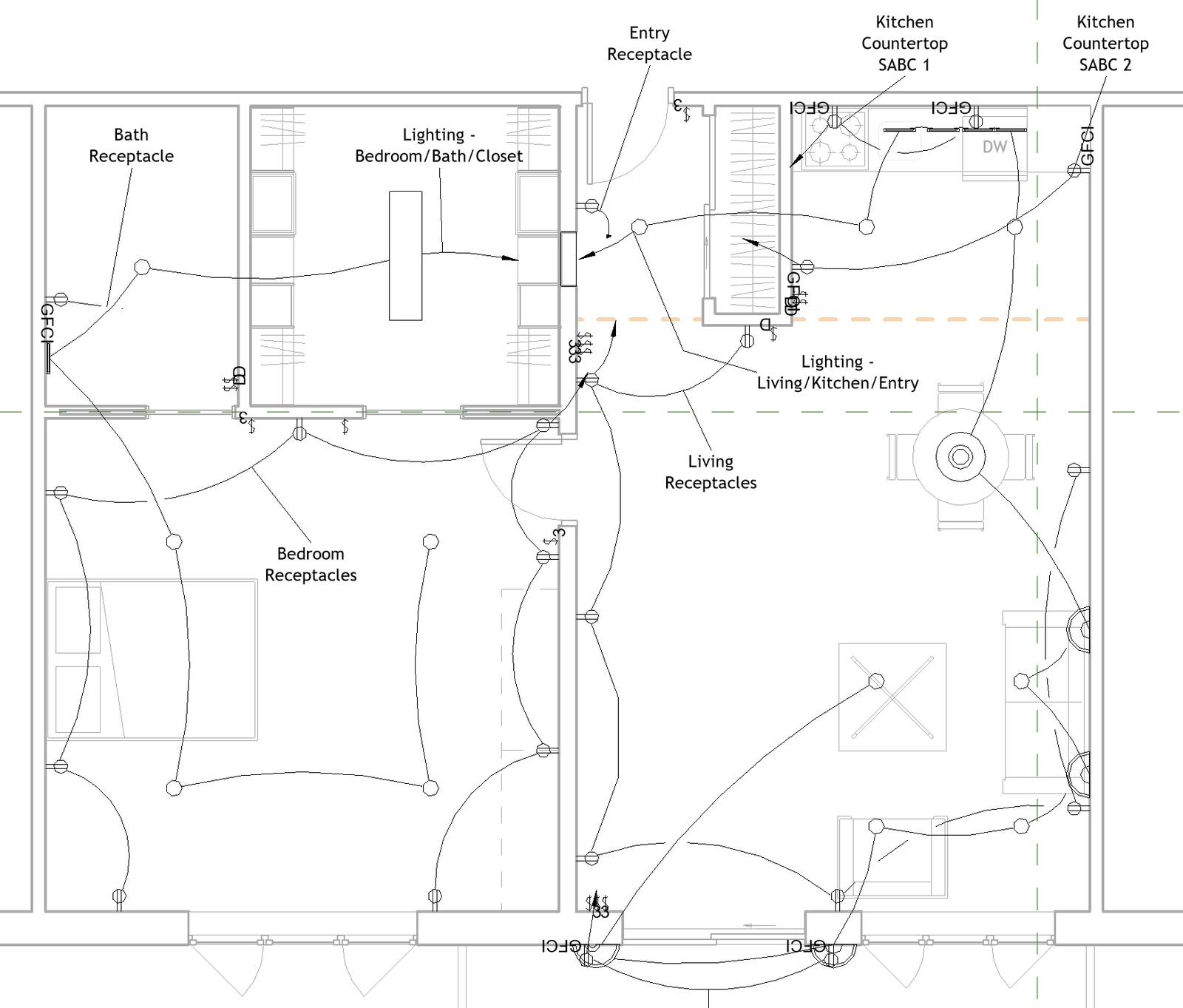
You can download this model file here:

Adding Power Circuits & Switch Systems for Lighting
Prompt | Tool Options
🟢 = Autodesk Asst
🔵 = Revit MCP
🟣 = Python + Dynamo |
Add power circuits and switch systems for the lighting fixtures in this residential unit:
• Match the lighting fixtures to switches based on the previous prompt that mapped out the switches to be created.
• Connect all power circuits to the electrical panel at the entry.
• Convert all temporary wires to Arc Wires.
• Show short 3’ home-run wires from the last devices on each circuit aimed at the panel.
• Tag the circuits with their Load Names.
As you work, send me a message after each step saying what you did and what you found. | 🟣 |
Claude Response
I'll check the panel, connectors, plan views and tag families first, then build the circuits, switch systems, wires and tags, messaging you after each step.
Step 1 – Electrical model reviewed. What I found:
- Panel A (entry west wall): 120/208V 3Ø 4W, 225A, 42 spaces. It already feeds circuits 1–8 (receptacles and the dishwasher). Those circuits already have arc wires and "Load Name and Current" wire tags in the L1 - Power and L1 - Lighting views.
- Already started for lighting:
- Circuit 9 "Lighting - Dwelling Unit" (20A): holds only the 4 Bedroom cans, with arc wires and a home run already drawn.
- Switch System (a): based on the bedroom-door 3-way but controlling only 1 of the 4 bedroom cans.
- Connected lighting load: 1,164 VA for all 23 fixtures (Revit family values), so one 20A circuit (1,920 VA at 80%) could carry the whole unit.
- API limit: Revit's API can extend a switch system but can't create a new one directly. I'll create the others through Revit's own Switch command and then attach each base switch.
Going with two circuits: circuit 9 renamed to Lighting - Bedroom/Bath/Closet, and a new circuit 10 Lighting - Living/Kitchen/Entry for the rest. I'll build the switch systems first while the fixtures are uncircuited, then the circuits, wires, home runs and tags. Starting with the switch systems now.
Now I'll zoom in on the bath switches so the pick is precise.
Now the entry can (k) and balcony sconces (h).
Step 2 – Switch systems done. All 11 switch systems (a–k) now exist, each based on the switch from the previous layout and holding the fixtures it controls. All 23 fixtures belong to a switch system.
- The Revit API can't create switch systems, so I used Revit's own Switch and Select Switch tools on your screen in the L1 - Lighting floor plan, checking each Switch ID as I went.
- System a already existed with 1 bedroom can. I added the other 3 cans through the API, briefly lifting them off circuit 9 and putting them back.
- 3-way and 4-gang pairs: a switch system takes one base switch. For a, e, f and k that's the first switch I listed; the partner 3-way carries the same Switch ID.
Next: power circuits.
The transaction committed; only the report line failed. Re-reading the circuits:
Step 3 – Power circuits done. Both lighting circuits are on Panel A at the entry, 20A, 120V:
- Circuit 9 – renamed Lighting - Bedroom/Bath/Closet: 7 fixtures (4 bedroom cans, bath can, vanity bar, closet panel), 372 VA.
- Circuit 10 – new, Lighting - Living/Kitchen/Entry: 16 fixtures (sofa sconces, seating cans, dining pendant, kitchen cans, under-cabinet strips, entry can, balcony sconces), 792 VA.
Both are well under the 1,920 VA continuous limit for a 20A breaker. Switches are left off the power circuits; they're tied to the fixtures through the switch systems. Next: wiring.
Step 4 – Arc wires and home runs done. Every circuit connection is now a permanent Arc wire in L1 - Lighting (Default wire type, the same as the existing lighting wires). I removed circuit 9's 4 old wires, which only covered the bedroom.
- Circuit 9: 6 fixture-to-fixture wires. The 3' home run starts at the closet panel, the device nearest the panel, and points at Panel A.
- Circuit 10: 15 fixture-to-fixture wires. Its home run starts at the entry can.
- Found: the entry can is only about 2' from Panel A, so a 3' run would have gone past the panel into the bedroom. I shortened that one to about 1'-8" so the arrow stops just short of the panel face.
Next: circuit tags.
The lighting now has switch systems, two circuits fed from Panel A at the entry, arc wires, home runs and Load Name tags. The model shows 0 warnings but isn't saved yet.
- Switch systems: all 11 (a–k) exist. Each one controls the fixtures from the earlier switch layout, and all 23 fixtures belong to one. For each 3-way pair, the system is based on one switch and its partner carries the same Switch ID, since a switch system takes only one base switch.
- The Revit API can't create switch systems, so I made them with Revit's own Switch and Select Switch tools on your screen.
- Circuits: both are 20A, 120V on Panel A.
- Circuit 9, renamed Lighting - Bedroom/Bath/Closet: 7 fixtures, 372 VA.
- Circuit 10, new, Lighting - Living/Kitchen/Entry: 16 fixtures, 792 VA.
- Wires: every wire on both circuits is an Arc wire in L1 - Lighting. I replaced circuit 9's 4 old bedroom-only wires.
- Home runs: each circuit has one, from the device nearest the panel, pointing at Panel A.
- Circuit 9: 3' long, starting at the closet panel.
- Circuit 10: shortened to about 1'-8". The entry can is only about 2' from the panel, so a 3' run would have gone past the panel into the bedroom.
- Tags: each home run has a "Wire Tag - Load Name and Current" tag showing its circuit's Load Name.
Two things to check:
- Fixture loads: the totals use the default values in each lighting family, not LED ratings, so the panel loads will change when you swap in real fixtures.
- Wire routing: the wires link each fixture to the next nearest one. They're schematic, not a planned conduit route, so some arcs cross rooms.
Claude Spreadsheet Summary of System Components
I'll pull the full electrical data from the model, then build the spreadsheet.
I've made the spreadsheet with four tabs covering all 10 circuits, 47 devices and fixtures, 11 switch systems and 15 switches. Every per-circuit load and device count matches the Revit model.
- Circuits: Panel A details at the top (120/208V Wye, 225A, 42 spaces, at the entry), then circuits 1–10. Each row has its load name, type, rating, load, current, how much of the 80% limit it uses, device and wire counts, and which switch systems it carries. The total connected load is 5,804 VA. The busiest circuit is circuit 2 (bedroom receptacles), at 75% of its limit.
- Devices & Fixtures: every receptacle, the dishwasher and every light fixture, with room, family and type, Revit element ID, circuit, load, Switch ID and notes.
- Switch Systems: systems a–k, each with what it controls, its base switch, any partner 3-way, fixture count and load, circuit, and fixture element IDs.
- Switches: all 15 switches, with room, type, whether each is the base switch or a partner 3-way, mounting height, and location and code notes.
The circuit and switch-system loads and counts are formulas that read the Devices & Fixtures tab, so they update when you change a load there. The lighting loads are still the Revit family defaults, not real LED ratings.