Videos
Resources to Download
Revit Models


Example - Fire Sprinkler System for Stacked Residential Units
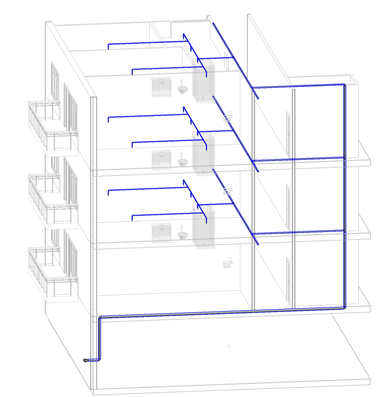
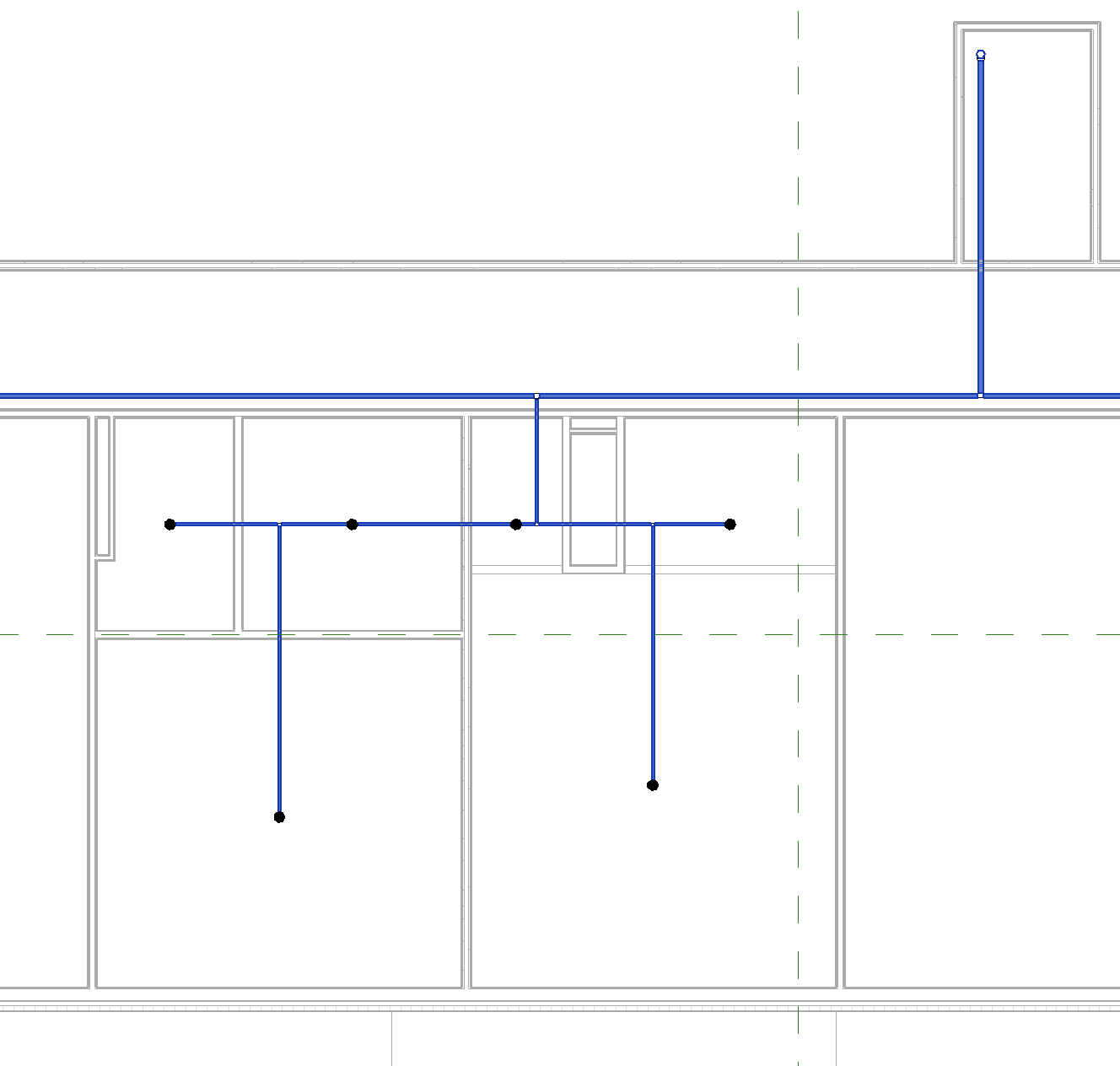
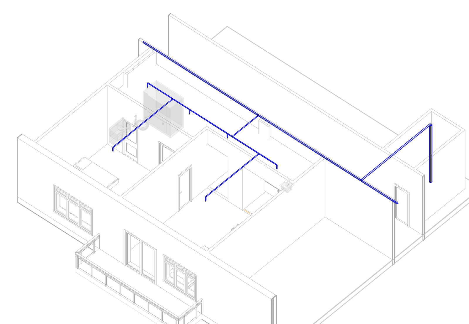
You can download this model file here:
AI Prompts
Creating a Fire Sprinkler System for Stacked Residential Units
Prompt | Tool Options
🟢 = Autodesk Asst
🔵 = Revit MCP
🟣 = Python + Dynamo |
Add a fire protection sprinkler system to the apartments in this multi-story residential building.
Fire Protection Sprinklers & Supply Lines:
• Place ceiling-mounted fire protection sprinklers at 10’ above the floor level in each unit, following all relevant code requirements for spacing and type.
• Route the supply piping for these sprinklers from each unit to a supply trunk line at the south side of the hallway.
• Run the horizontal trunk supply line the full length of the hallway.
• Connect the horizontal trunk lines at each level to a riser in the mechanical room at each level.
• Repeat this piping design on Levels L1 through L3.
Garage Level Connections:
• Run a horizontal trunk line at 10’ above the Level Garage floor level that connects the base of the vertical riser for the piping system to an external Fire Department Connection at the front of the exterior wall at the garage level.
As you work, send me a message after each step saying what you did and what you found. | 🟣 |
Claude Response
I'll start by connecting to Revit and inspecting the open model (levels, rooms/units, hallway, mechanical rooms, and available sprinkler/pipe families) before placing anything.
Step 1 – Model check done. Revit is connected to 261104 Piping System – Stacked Residential – Fire Sprinklers.
- Levels: Garage (−12'), L1 (0'), L2 (12'), L3 (24'), L4 (36').
- Rooms: L1 has one unit's rooms (Closet, Bath, Bedroom, Living, Kitchen) plus a Hallway and Mechanical Room; L2 and L3 only have Hallway + Mechanical Room rooms placed. No sprinklers or pipes exist yet. Next: reading room/wall geometry and checking for loaded sprinkler and pipe types.
Step 2 – Geometry and content check done. What I found:
- One dwelling unit per level (L1–L3, stacked identically): about 32.8' × 25.7' between x = −31.0' and +1.8', with a Bedroom, Living (plus entry), Kitchen, Closet, Bath, and a ~14 sf pantry. The unit door opens north into the hallway.
- Hallway: runs east–west the full building (~119' long). Its south wall (the unit side) is at y = 9.71'.
- Mechanical Room: 6' × 10.5' room off the north side of the hallway, at x 7–13'. It is stacked on L1–L3.
- Front of building is the south wall (y = −16.0'), where the unit's exterior door is. The Garage level has only that south wall modeled.
- Ceiling heights: Bedroom and Living are 10' to the structure above. A 9'-0" ceiling covers the Closet, Bath, Kitchen and entry band. Heads at 10' in those rooms would sit above that ceiling. I'll follow your 10' instruction and flag this again at the end.
- Missing content: no sprinkler, FDC or fire-protection pipe types are loaded in the project. The Revit 2027 Imperial library has Sprinkler – Pendent and Fire Department Connection – 2 Way – Flush Outlet Body, which I'll load. The Fire Protection Wet piping system already exists.
Next: loading those families and setting up a fire-protection pipe type.
Step 3 – Content loaded.
- Loaded Sprinkler – Pendent (½" type) and Fire Department Connection – 2 Way – Flush Outlet Body. The FDC has a 4" inlet and two 2½" hose outlets.
- Created pipe type "Fire Protection – Steel Sch 40". It uses Schedule 40 carbon steel with generic (threaded) elbows, tees, crosses, caps and transitions, assigned to the Fire Protection Wet system.
- Probe placement showed the sprinkler's pipe connector is at its insertion point. Setting "Elevation from Level" = 10'-0" therefore puts the head connection exactly at 10' AFF.
Head layout I'm using, applied identically on L1–L3. It follows NFPA 13R-style rules: ≤20' between heads, ≤10' to any wall, ≥8' between heads in the same space, ~400 sf max per head.
- Bedroom: 1 head, centered
- Living: 1 head, centered in the main space
- Entry: 1 head (the entry's north end is >10' from the living head)
- Kitchen: 1 head
- Closet (90 sf, so it needs a head): 1 head
- Bath: 1 head (13R would allow omitting a bath ≤55 sf; I included it to be conservative)
- Pantry (~14 sf): none (under the 24 sf exemption)
Next: placing the 18 heads.
Step 4 – Sprinklers placed. I placed 18 pendent heads, 6 per unit on L1, L2 and L3. Each head's connection is at exactly 10'-0" AFF (absolute 10', 22', 34'). Each head is tagged in Comments, e.g. "FP-L2-Bedroom". All four north-band heads (Bath, Closet, Entry, Kitchen) sit on one line at y = 4.85', so a single straight branch main can serve them.
Next: unit branch piping and the hallway trunk on each level.
Step 5 – Unit branches and hallway trunks built on L1, L2 and L3. All connected with 0 warnings. On each level:
- Branch piping (1") runs at 10'-9" AFF, just above the heads and below the 11' slab:
- an east–west branch main through the north band of the unit (Bath → Closet → Entry → Kitchen)
- two branch arms south to the Bedroom and Living heads
- a short 1" drop from the branch down to each head's 10' connection
- Unit feed (1") leaves the unit near the entry door and runs north to the trunk.
- Hallway trunk (2") runs the full hallway length, from x = −59.4' to +58.7'. It sits 0.6' off the south hallway wall (y = 10.5') at 10'-9" AFF. Both ends are capped. Transitions were inserted automatically at the 2"×1" tee.
- Mech-room branch (2") tees off the trunk at x = 8' and runs north through the hallway's north wall into the Mechanical Room. It stops at the riser location (8.0', 25.5') in the room's northwest corner, clear of the door.
Next: the vertical riser in the mechanical room stack.
Step 6 – Riser installed. A 4" vertical riser now runs up the Mechanical Room stack at (8.0', 25.5'). It goes from 10' above the Garage floor up to L3's piping elevation. Each level's 2" branch ties in with a 4"×2" reducing tee on L1 and L2 and an elbow at the top on L3.
Issue found and fixed: the first attempt failed because the new pipe type had inherited size limits from its source type: fittings only up to 2½", and steel segments only 3" and up. I reset all routing-preference rules on Fire Protection – Steel Sch 40 to cover all sizes. The tees then inserted cleanly, with 0 warnings.
Next: the garage-level trunk and the FDC.
The sprinkler system is modeled and fully connected on L1–L3 and the Garage: one Fire Protection Wet system, 63 pipes and 69 fittings, no open ends and 0 warnings. I also added a 3D view, FP – Sprinkler System 3D, that shows the whole system in red. I haven't saved the model, so you can review it first.
What's in the model
- Sprinklers: 18 pendent heads, 6 per unit on each of L1–L3, with the connection at 10'-0" above the floor. The Bath, Closet, Entry, Kitchen, Bedroom and Living each get one head. The pantry has none, because it's small enough to be exempt.
- Unit piping: 1" branch piping in each unit, run at 10'-9" so it sits just above the heads and below the slab. A short drop connects each head.
- Hallway trunks: a 2" trunk on each level runs the full hallway length along the south side, capped at both ends. Each unit's feed tees into it.
- Riser: each trunk connects to a 4" riser in the Mechanical Room's northwest corner. The riser runs from 10' above the Garage floor up to L3.
- Garage and FDC: a 4" trunk at 10' above the Garage floor runs from the base of the riser south to the front (south) wall. It then drops to a 2-way Fire Department Connection set in that wall at 3'-0", with its hose outlets facing out.
Items you should review
- The 9' ceiling. Four heads (Closet, Bath, Kitchen, Entry) end up above the 9'-0" ceiling in those rooms, where they wouldn't protect the room. I kept 10' because that's what you specified. I'd recommend lowering those four heads to just below the ceiling, or switching them to a recessed pendent hosted on the ceiling.
- The FDC drop. Fire department connections normally need to sit 18"–48" above grade, so I dropped down from the 10' trunk to put the FDC at 3'-0". If you want it at 10', it's a quick change.
- Other areas codes would likely require. The hallways, mechanical rooms and garage have no heads, because you only asked for the units. The garage piping is a wet system; if the garage is unheated, it would need a dry or antifreeze system instead.
- Components not modeled. There's no check valve at the FDC, and no control valve, flow switch or drain at the riser or on the floor branches.
- Sizing and heads. Pipe sizes are nominal and not hydraulically calculated. The sprinkler is a generic Revit library family, not a listed residential head.
I also had to widen the size range on the new fire-protection pipe type, because its fittings were initially limited to 2½" and the larger tees wouldn't insert.
I can fix the four heads under the ceiling, or add hallway and mechanical room heads, if you'd like.
Claude Spreadsheet Summary of Systems Created
I’ve made Fire_Sprinkler_System_Summary.xlsx from the live Revit model data. The system is a single Fire Protection Wet system with 18 heads, 63 pipe segments (650.1 ft in total), 69 fittings and one fire department connection (FDC).
The workbook has six tabs:
- Summary: system info, element counts, pipe length by run and level, pipe length by size, fittings by type and level, and heads by room and level. These are all formulas off the detail tabs, so they update if you edit the data.
- Pipe Schedule: every pipe segment, with its Revit element ID, run, size, length, start and end points, height above the floor, and orientation.
- Fittings: every tee, elbow, transition and cap, with size and location.
- Sprinklers: all 18 heads, with their tag, room and the elevation of the pipe connection.
- Equipment: the FDC.
- Design Notes: the layout rules I followed, plus the open items from the modeling work, such as the four heads sitting above the 9' ceiling.
By size, the piping is 170.6 ft of 1" in the units, 396.6 ft of 2" for the hallway trunks and the branches to the riser, and 82.9 ft of 4" for the riser and the garage run to the FDC.