Videos
Workflow
Load MEP Versions of Lighting Device Families
Many useful families are already loaded in the Imperial Multi-Discipline Template.
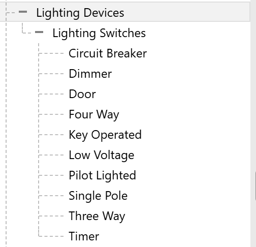
- Load additional families from Library > Electrical > MEP > Electric Power > Terminals
Place Lighting Switch Components
For guidance about Lighting Switch Types and Placement:
Wall Switches: Types and Placement Guidelines- Open a Lighting Plan or Power Plan view
- Floor Plans look down toward the floor.
- Ceiling Plans look up toward the ceiling.
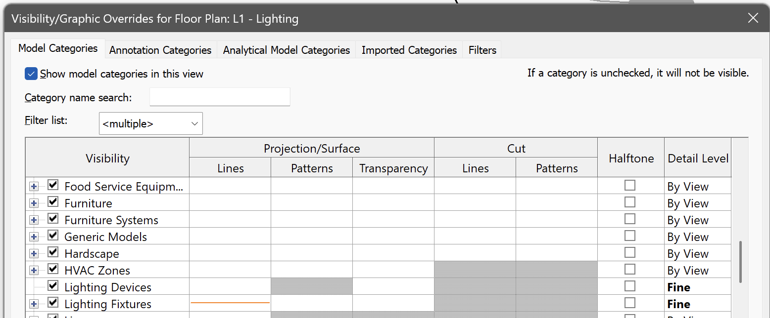
- Set the Visibility/Graphics Overrides for the view to display the lighting switch symbols (versus the 3D geometry).
- The Lighting Plan view in the Imperial Multi-Discipline template are set to show the lighting devices using the Fine Detail Level (which shows the 3D geometry) rather than the switch symbol.
- Change this setting to By View or Coarse to see the symbols instead.
- Open Systems > Electrical > Device > Lighting
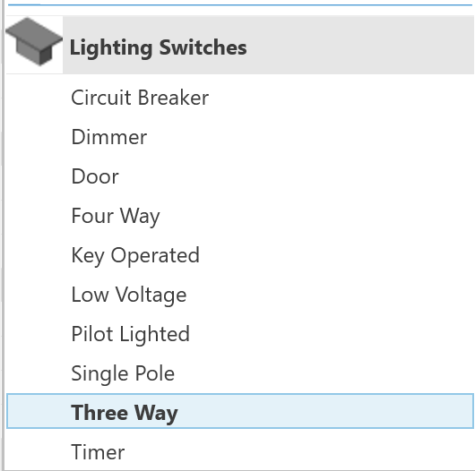
- Choose a Lighting Switch family from the Type Selector.
- Select the Type based on the features required.
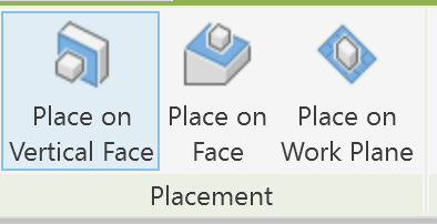
- Choose a placement option in the Ribbon.
- Place on Vertical Face
- Wall switches are typically placed on the vertical face of a wall.
- Place on Face
- Place on Work Plane
- Click in the drawing area to select placement locations.
- Move the cursor over the vertical face of a wall in the drawing area.
- Click to place the switch.
AI Prompts
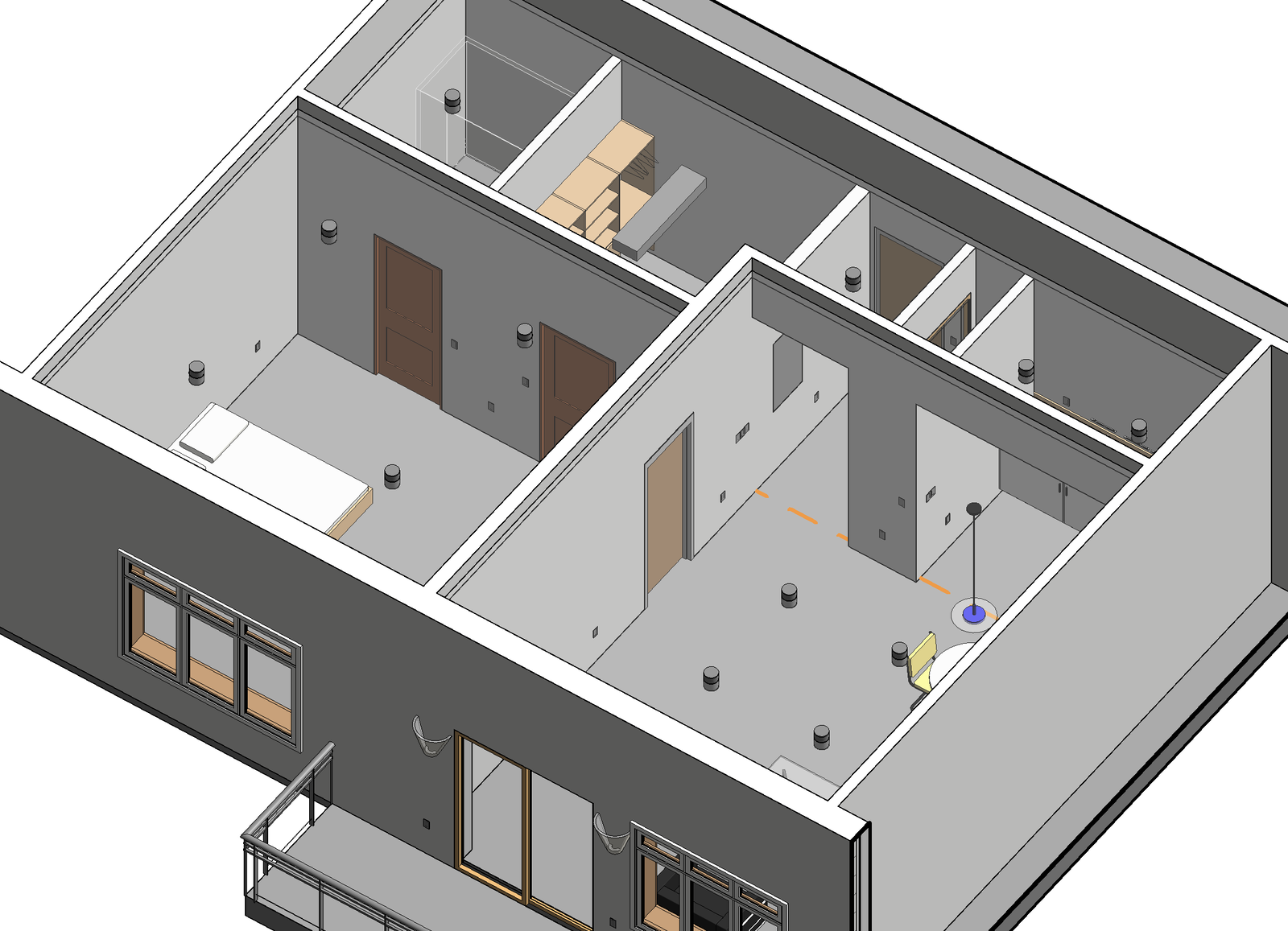
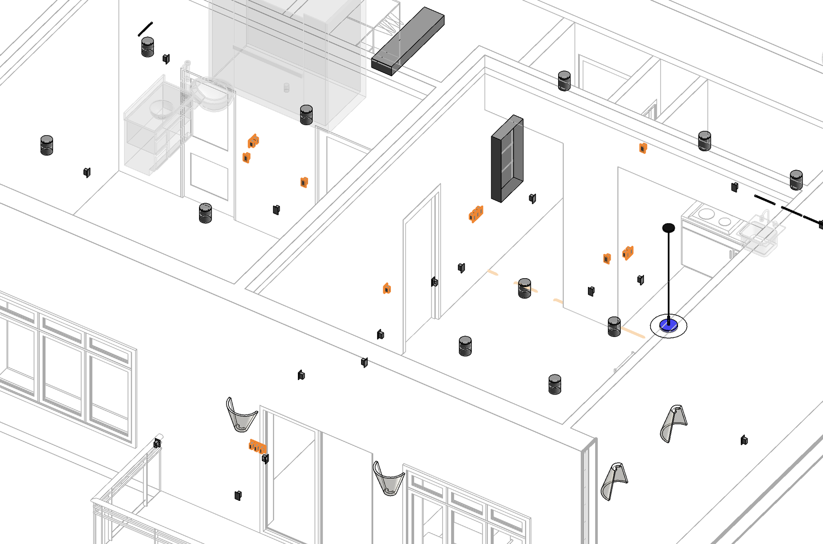
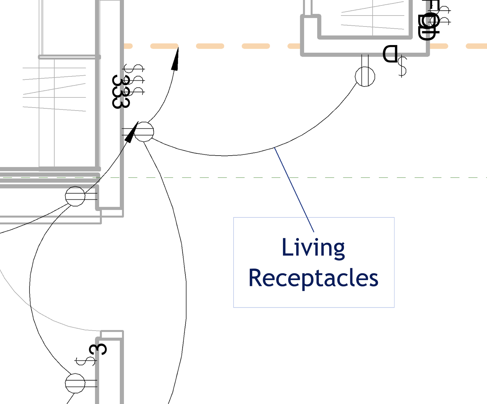
You can download this model file here:

Adding Lighting Switches
Prompt | Tool Options
🟢 = Autodesk Asst
🔵 = Revit MCP
🟣 = Python + Dynamo |
Add switches to control the lighting fixtures in all rooms in this residential unit:
Bedroom:
• Place three-way switches near the bedroom entry and the bathroom door to control the recessed can lights in the bedroom.
Bathroom:
• Place a dimmable switch with a vacancy sensor to control the lighting bar above the vanity.
• Place another dimmable switch with a vacancy sensor to control the recessed can light.
Closet:
• Place a switch outside the closet door to control the ceiling-mounted LED panel in the closet.
Living Area:
• Place a three-way switch near the entry to control the wall-mounted sconce uplights on the wall behind the sofa.
• Place another three-way switch adjacent to it to control the 4 recessed can lights over the seating area.
• Place the opposite end switches for these three-way branches near the sliding door to the balcony.
• Place a dimmable switch near the dining table to control the hanging pendant light above it.
• Place a switch to control 2 waterproof LED sconce lights on the balcony adjacent to the sliding door.
Kitchen:
• Place a dimmable switch with a vacancy sensor to control the 2 recessed can lights in the kitchen.
• Place another dimmable switch with a vacancy sensor adjacent to it to control the undercabinet LED strip lights.
Entry:
• Place a three-sway switch to control the recessed can light in the entry. Place the opposite end switch for this three way branch near the other switches at the entry to the living area.
Use all applicable codes when determining switch placement locations.
As you work, send me a message after each step saying what you did and what you found. | 🟣 |
Claude Response
I'll check the doors, walls and switch families, then place the switches room by room. I'll message you after each step.
Step 1 – Doors, walls and switch families checked.
- Door swings (from the plan swing arcs):
- Entry door is hinged on the west, so its latch side is east.
- Bedroom door is hinged on the north and swings into the bedroom, so its latch side is south.
- Bath and closet are pocket doors. Their pockets run west of the bath opening and east of the closet opening, so no switch box can go on those stretches of wall.
- Open plan: the 3'-tall walls between the Entry, Kitchen and Living are bulkheads sitting at 9'–12', so those rooms are open to each other below 9'. The only wall surfaces near the entry-to-living opening are the Living west wall and the coat-closet walls.
- Fire-rated walls: the corridor wall (entry door), the sofa wall and the bath west wall are 2-hour partitions. Switch boxes in them need membrane-penetration treatment (IBC 714.4.2).
- Switch families: Lighting Switches has Three Way, Single Pole and Dimmer types. There is no vacancy-sensor type, so I'll create a Dimmer - Vacancy Sensor type.
Codes I'm applying:
- Mounting at 44" AFF to centre, so operable parts stay within 48" (Fair Housing Act / ANSI A117.1).
- About 6" off the latch-side door frame, never behind a door swing or over a pocket.
- NEC 404.4(C): no switches in the shower space.
- NEC 404.2(C): neutral at each switch box, which the sensor dimmers need.
- Energy code (e.g. CA Title 24 §150.0(k)): vacancy sensors or dimmers, and under-cabinet lighting switched separately.
Step 2 – Bedroom done. I placed two 3-way switches controlling the 4 bedroom cans, Switch ID a on the switches and in the cans' Comments.
- At the bedroom entry: on the bedroom side of the shared wall, latch side of the door (south), about 7" off the frame. It's clear of the door swing and about 1'-6" short of the dresser.
- Near the bathroom door: on the bedroom side of the bath/closet wall, just east of the bath opening. That keeps it off the pocket, which runs west of the opening.
Both are at 44" AFF to centre. Next: Bathroom.
Step 3 – Bathroom done. I created a Dimmer - Vacancy Sensor switch type and placed two of them as a 2-gang on the bath's east wall, just inside the pocket door at 44" AFF. The pocket door leaves almost no wall beside the opening on its own wall, so the east wall is the first usable surface you reach.
- Switch b: vanity light bar
- Switch c: recessed can
The switches are more than 5' from the shower threshold, well outside the shower space (NEC 404.4(C)). The vacancy sensors cover the CA Title 24 requirement for a bathroom vacancy sensor. Next: Closet.
Step 4 – Closet done. I placed one single-pole switch (Switch d) outside the closet, on the bedroom face of the wall just west of the 36" pocket door at 44" AFF. The pocket runs east of the opening, so the west side is the only place a box can go. It's about 5" off the door trim and 3' from the bedroom 3-way, so the two read as separate controls. Next: Living area.
Step 5 – Living area done.
- Entry end of the 3-ways: on the Living west wall, just inside the opening from the Entry:
- Switch e – sofa sconces
- Switch f – seating-area cans
- Balcony end: a 3-gang on the inside face of the exterior wall, in the 14" between the sliding-door frame and the room corner:
- Switch e – sconces (3-way)
- Switch f – cans (3-way)
- Switch h – balcony sconces (single pole, nearest the door)
- Dining pendant (Switch g): a standard dimmer on the coat-closet wall facing the dining area, about 3' from the table edge. I chose this non-rated wall over the 2-hour sofa wall to avoid another rated-wall penetration.
I left the top slot by the corner for the entry can's second 3-way, so all three gang together.
Found: the balcony-end gang sits roughly back-to-back with the west exterior sconce box. That's allowed, but the exterior wall's air barrier will need sealing at both boxes. Next: Kitchen.
Step 6 – Kitchen done. I placed two Dimmer - Vacancy Sensor switches side by side as a 2-gang on the kitchen's west wall, just inside the opening from Living at 44" AFF:
- Switch i: the 2 recessed cans
- Switch j: the under-cabinet strips
The gang is about 2'-6" from the counter end, so it's clear of the countertop and backsplash. Keeping the under-cabinet strips on their own switch meets the energy-code rule that under-cabinet lighting be switched separately. Next: Entry.
Step 7 – Entry done and all switches verified.
- Entry can (Switch k):
- One 3-way inside the entry door on the latch (east) side, about 6" off the frame. It's on the 2-hour corridor wall, so it's noted for a listed box or putty pad (IBC 714.4.2).
- Its other end completes the 3-gang at the living-area entry, together with sconces e and cans f.
- Verification: all 15 switches are hosted on wall faces at 44" AFF and face into the right rooms, and none overlap each other. Every one of the 23 fixtures now has a Switch ID, and the model shows 0 warnings.
- The only clash flagged was the bath dimmers against the bath pocket door's bounding box. That box comes from the door's non-solid symbolic geometry; no solid part of the door reaches the switches, so it isn't a real conflict.
All 15 switches are placed, and every fixture is assigned to one; the model isn't saved yet.
Each switch carries a Switch ID (a–k), and the same letter is added to the Comments of the fixtures it controls.
ID | Controls | Switch type | Location |
a | Bedroom cans | 3-way ×2 | Bedroom door (latch side); bedroom wall east of bath door |
b | Bath vanity bar | Dimmer + vacancy sensor | Bath east wall inside door, 2-gang with c |
c | Bath can | Dimmer + vacancy sensor | Same 2-gang as b |
d | Closet panel | Single pole | Bedroom side, west of closet door |
e | Sofa sconces | 3-way ×2 | Living-entry 3-gang; balcony-door 3-gang |
f | Seating cans | 3-way ×2 | Same two 3-gangs as e |
g | Dining pendant | Dimmer | Coat-closet wall facing the dining area |
h | Balcony sconces | Single pole | Balcony-door 3-gang, nearest the door |
i | Kitchen cans | Dimmer + vacancy sensor | Kitchen west wall, 2-gang with j |
j | Under-cabinet strips | Dimmer + vacancy sensor | Same 2-gang as i |
k | Entry can | 3-way ×2 | Inside entry door; living-entry 3-gang |
The placements follow these code points:
- 44" AFF to centre, so the controls stay within 48" (Fair Housing Act / ANSI A117.1).
- Latch side of each door, never over a pocket.
- Nothing in the shower space (NEC 404.4(C)).
- Neutral at each box (NEC 404.2(C)), which the sensor dimmers need.
- Vacancy sensors in the bath and kitchen, with the under-cabinet lights on their own switch (CA Title 24 §150.0(k)).
To check before issue:
- Fire-rated walls: the entry-door switch is on the 2-hour corridor wall, so its box needs a listed box or putty pad (IBC 714.4.2).
- Balcony switches: the 3-gang by the balcony door sits nearly back-to-back with the west exterior sconce box, so seal the air barrier at both.
- Balcony sconce controls: if the project is under CA Title 24, exterior lights also need a photocell with motion sensor, or an astronomical time clock, in addition to switch h.
- New switch type: Dimmer - Vacancy Sensor is a duplicate of the generic dimmer. Swap in a manufacturer family if you have one.
Want me to save the model, or add a switch schedule tab to the fixture spreadsheet?
Claude Spreadsheet Summary of Fixtures Placed
I've made the switch schedule as a new spreadsheet with three tabs:
- Switches: one row per Switch ID (a–k), with what it controls, switch type, quantity, location, and the Revit element IDs of each switch and its fixtures. The total row comes to 15 switches.
- Code basis: the mounting-height, door-placement, NEC and Title 24 points, each with how it was applied.
- To check: the follow-ups before issue, including saving the model.