Radiators and radiant floors are hydronic systems that use water for highly efficient heat transfer.
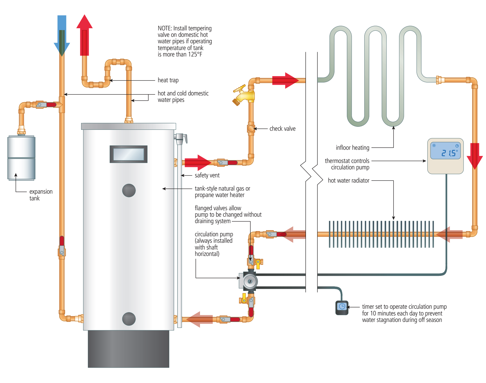
Hot Water Radiators
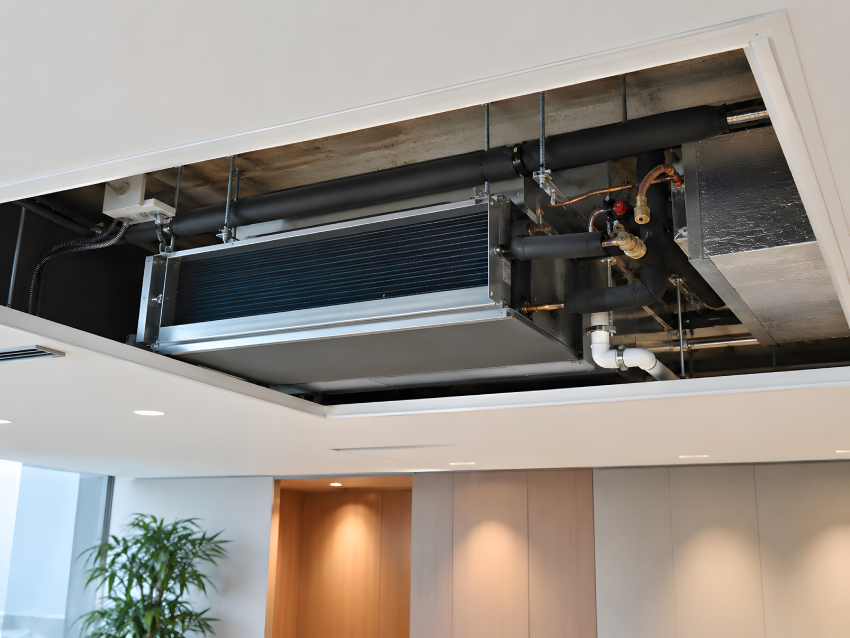
- A water heater provides hot water that is pumped through the radiator units.
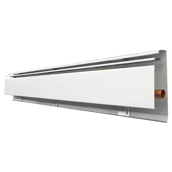
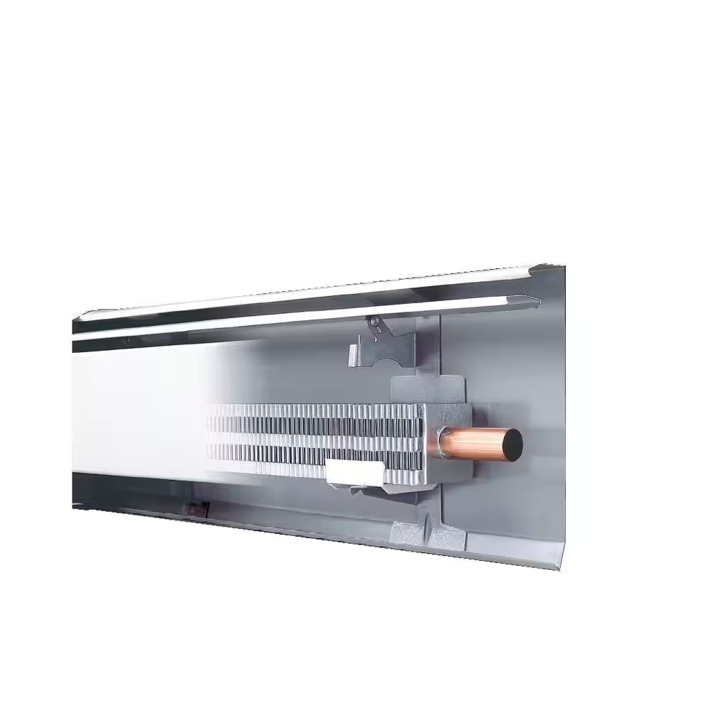
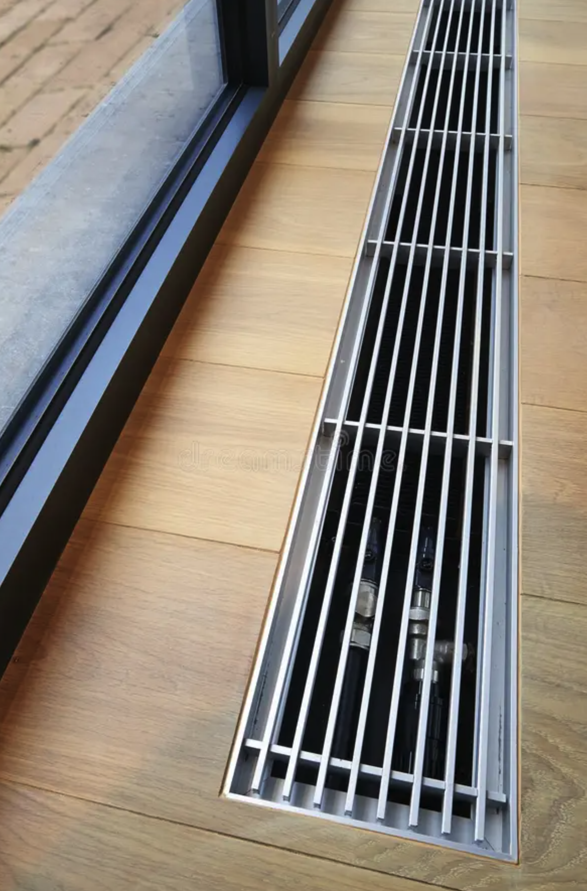
- Radiators can be mounted on walls or recessed into channels in the floor.
Radiant Floor Systems
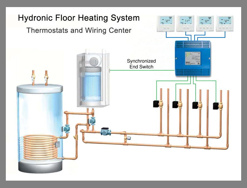
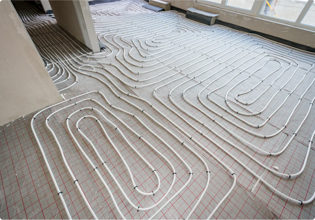
- A water heater provides hot water that is pumped through the system.
- Thermostatically-controlled switches determine how much water is pumped through each floor zone.
Example 1 - Hot Water Radiators
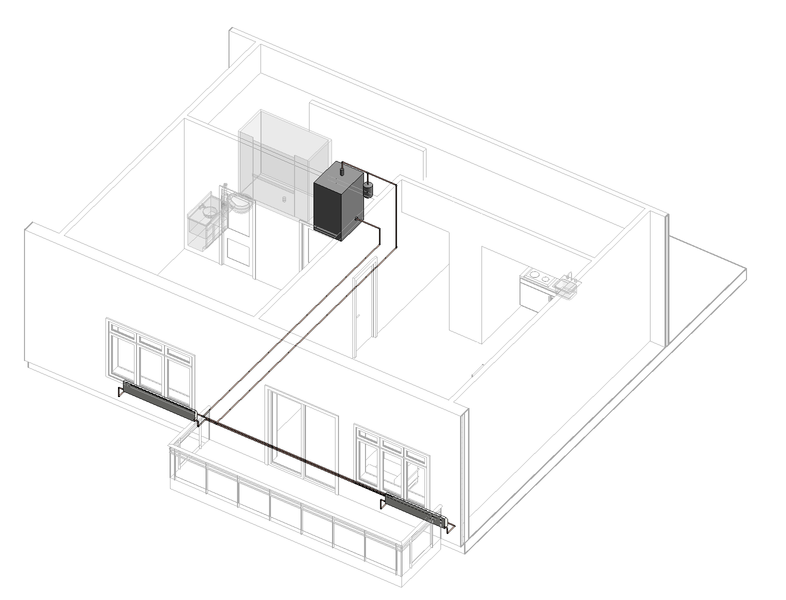
Note: The water heater and expansion tank could be located in a remote location — in a basement or mechanical room.
You can download this file here:

AI Prompts
Creating a Hot Water Radiator System
Prompt | Tool Options
🟢 = Autodesk Asst
🔵 = Revit MCP
🟣 = Python + Dynamo |
Add a hot water radiator system to this residential apartment unit.
Radiators:
• Place wall-mounted radiators along the exterior wall of the bedroom and living areas.
Hot Water Source:
• Route the piping to a water heater in a mechanical room out of view. | 🟣 |
Claude Response
I'll look at the open Revit model to find the unit's rooms, exterior walls and a mechanical space, then place the radiators, water heater and piping.
Radiator and boiler families are loaded. Let me inspect their geometry and pipe connectors before placing.
The door type needed activating; let me check that the partial attempt didn't leave anything behind.
Nothing was left behind. Running the full build with proper rollback this time.
Built. Now verifying connections, systems and warnings.
Everything is connected with zero model warnings. Revit split each loop into several duplicate system records, so I'll consolidate those into one supply and one return system.
Consolidating would orphan some pipes, so I left the systems as Revit made them (all connected, no warnings). Now a visual check.
The hydronic radiator system is now in the model, with all pipes connected and no Revit warnings.
Radiators
- Bedroom: a 6' fin-tube radiator on the exterior wall, centered under the window (about 5,460 Btu/h).
- Living area: a 5' fin-tube radiator under the living-room window (about 4,550 Btu/h). It's shifted slightly east of the window's center so it doesn't run into the lounge chair.
- Both sit about 11" tall, below the 20" window sills.
Mechanical room
- The unit had no mechanical space, so I made one at the back of the walk-in closet. It has a new 4½" partition and a 30" pocket door, matching the existing closet doors.
- To make room, both closet shelving runs are shortened from about 9'-4" to about 5'-10".
- Water heater: the project has no residential water heater family loaded, so I used the loaded Boiler family as a new type, "Water Heater - Hydronic 3/4in". It's against the west wall of the new room. A 2-gallon expansion tank hangs off the supply header beside it.
Piping
- All piping is ¾" copper.
- Supply rises off the top of the heater, crosses overhead inside the mechanical room, then drops into the floor.
- Supply and return then run south below the finished floor, at two different depths so they don't clash. They branch along the exterior wall to each radiator.
- Nothing is exposed in the bedroom or living area. That's also why the piping doesn't show in the L1 plan views; it's visible in 3D or a section.
Worth reviewing
- Combustion and clearances: the room is about 9'-7" × 3'-1". A gas-fired heater will need a sealed-combustion or electric unit, and you should check the manufacturer's service clearances.
- Circulator: none was added, on the assumption that the heater has a built-in pump.
- Pipes in the floor: these run through the 12" generic floor, so confirm that works with your slab or topping build-up.
- Not saved: the model is unsaved, and the whole change is one undo step ("Add hydronic radiator system").
Example 2 - Radiant Floor System
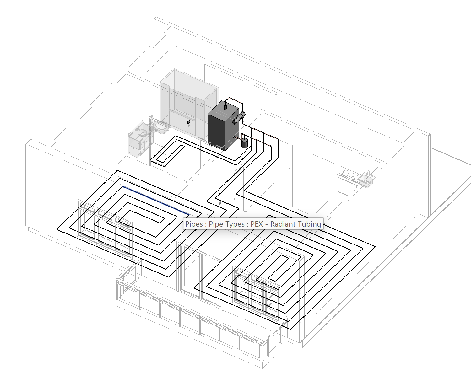
Note: The water heater, expansion tank, and valves could be located in a remote location — in a basement or mechanical room.
You can download this file here:
AI Prompts
Creating a Radiant Floor System
Prompt | Tool Options
🟢 = Autodesk Asst
🔵 = Revit MCP
🟣 = Python + Dynamo |
Add a hot water radiant floor system to this residential apartment unit.
In-Floor Tubing:
• Provide three zones with thermostats in each room:
◦ Living Area
◦ Bedroom Area
◦ Bathroom
Hot Water Source:
• Route the tubing to a water heater in a mechanical room out of view. | 🟣 |
Claude Response
I'll check the open Revit model to see the apartment layout before laying out the radiant zones.
Layout checks out (no tube crossings, ~555 ft of tubing across three counterflow loops). Now building the pipe types and positioning equipment in the mechanical closet.
All 92 pipe runs and fittings connected cleanly. Now the thermostats and making the in-slab tubing visible on the mechanical plan.
The radiant floor system is in the model, on the L1 - Mechanical plan. All 184 pipe connectors are joined with none left open, and the three zones are color-coded: red for Living, blue for Bedroom, green for Bathroom.
Hot water source. The heat source is a hydronic water heater (WH-1). It sits in the small enclosed room behind the walk-in closet, which you reach through the 30" pocket door, so it's out of view. That room also holds:
- the circulator (P-1)
- a 2-gallon expansion tank (ET-1)
- ¾" copper supply and return manifolds, with one branch per zone
In-floor tubing. Each zone is a ½" PEX loop in a counterflow spiral, about 1½" below finished floor:
Zone | Thermostat | Spacing | Tubing |
RF-1 Living Area | T-1, east face of the bedroom/living partition | 12" o.c. | ~280 ft |
RF-2 Bedroom Area | T-2, west face of the same wall | 12" o.c. | ~235 ft |
RF-3 Bathroom | T-3, bathroom east wall | 6" o.c. | ~45 ft |
- Bathroom tubing stays clear of the shower, WC and vanity.
- Leaders run in the slab from the mechanical room, through the walk-in closet, to each zone, and none of them cross.
- Thermostats are at 5'-0" AFF.
- Tagging: every pipe and fitting carries its zone name in Comments, which is what drives the view filters.
Model housekeeping:
- I added two pipe types, "PEX - Radiant Tubing" and "Hydronic - Copper".
- The view range on the L1 Mechanical and Plumbing plans now reaches 6" below the level, so the in-slab tubing shows.
- The model is not saved, so you can review it before committing.
Not modeled:
- Zone control: there were no zone valve or zone controller families loaded, so the thermostats aren't wired to anything in the model. You'll need either zone valves on each supply branch or one circulator per zone.
- Mixing valve: I'd add a thermostatic mixing valve after the heater, because radiant slabs want about 100–120°F water.
- Equipment sizes: the circulator and heater are generic library types. Size them to the actual heat load.