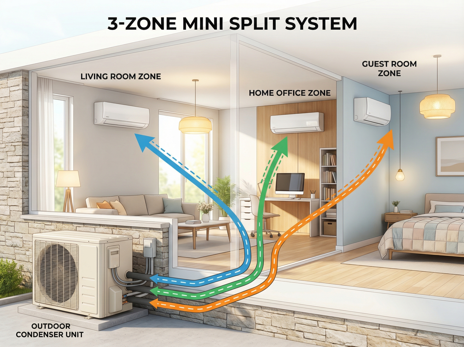
Mini-split systems are often used to provide room-level HVAC control to residential and hotel units.
Ductless Mini-Split Systems
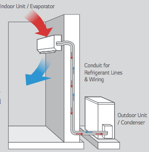
Ductless Mini-split systems have:
- An outdoor condenser unit (typically mounted on a ground pad, balcony, or a rooftop).
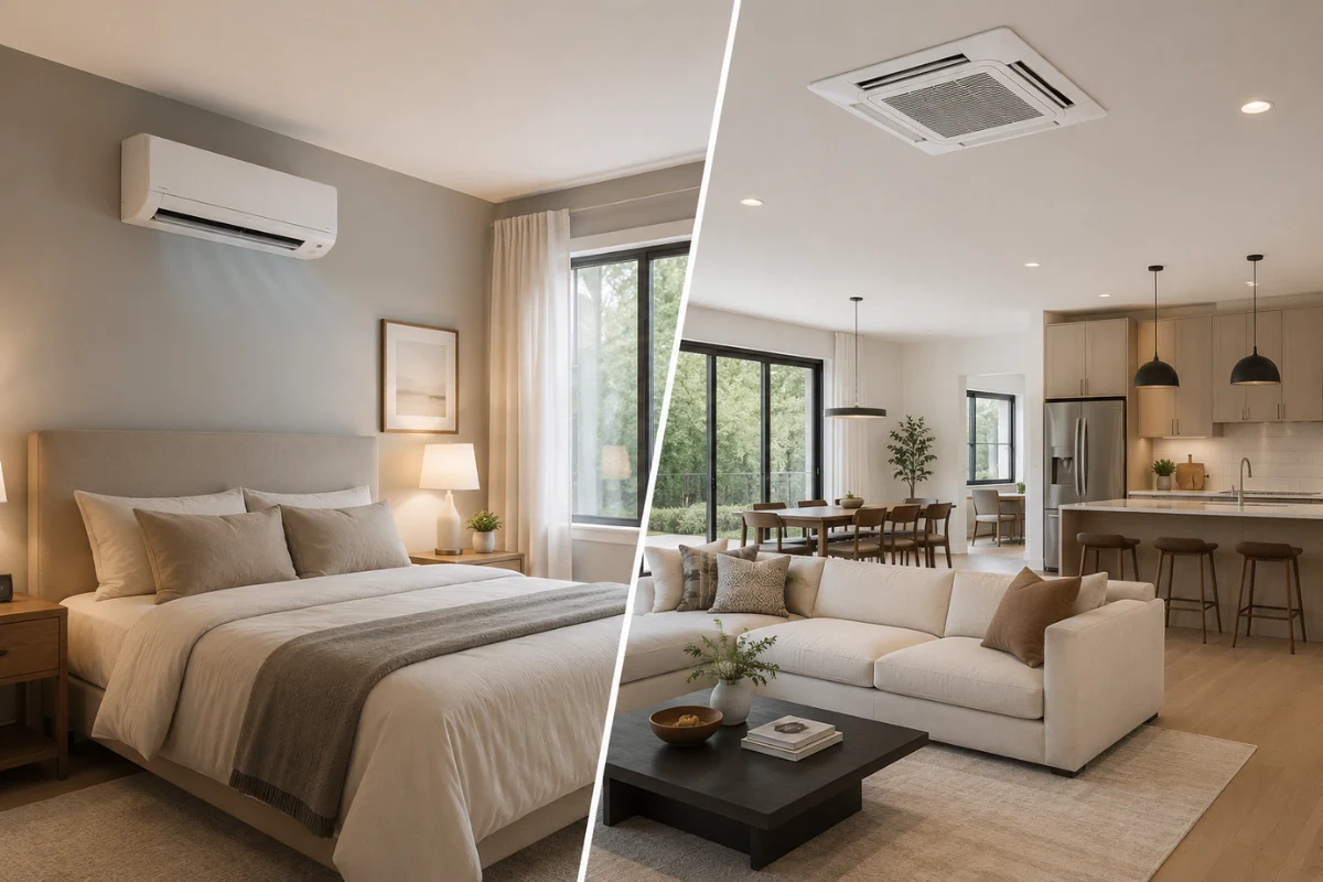
- Self-contained “cassettes” mounted on the walls or ceiling of the rooms they service.
Ducted Mini-Split Systems
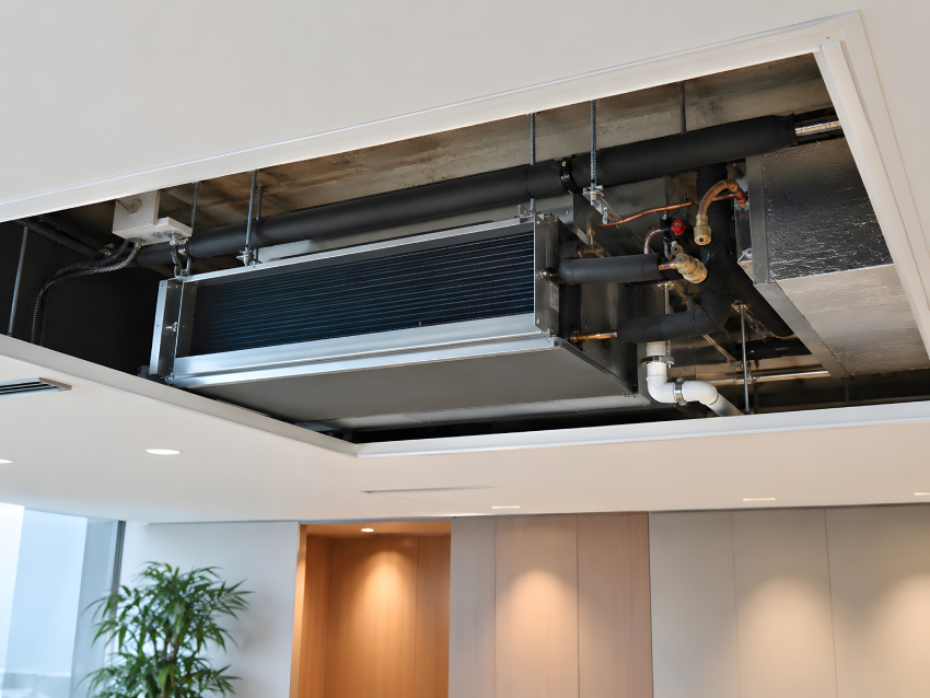
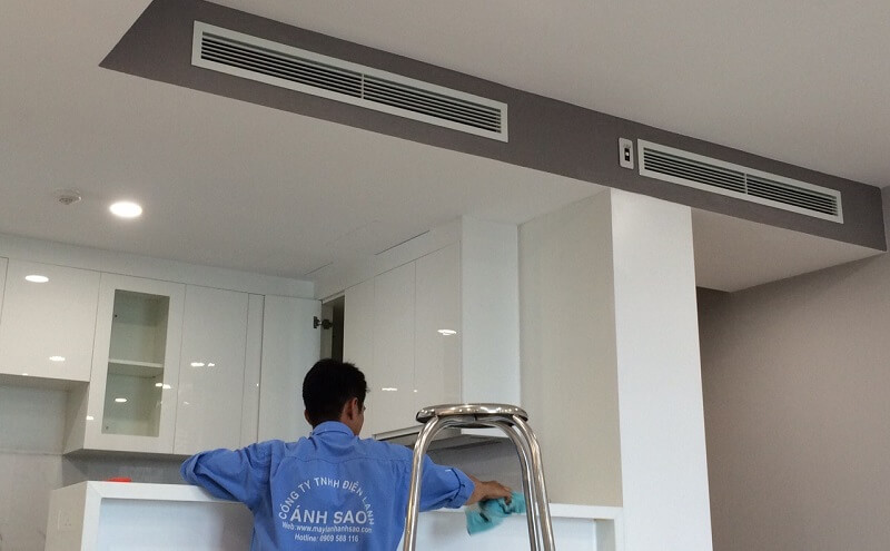
Ducted mini-split systems are similar, but conceal the fan coil unit in a plenum space or soffit (lowered ceiling area).
- The fan coil unit is hidden.
- Ducts route the supply air to registers in the ceiling or soffit walls.
Example 1 - Ductless Mini-Split System
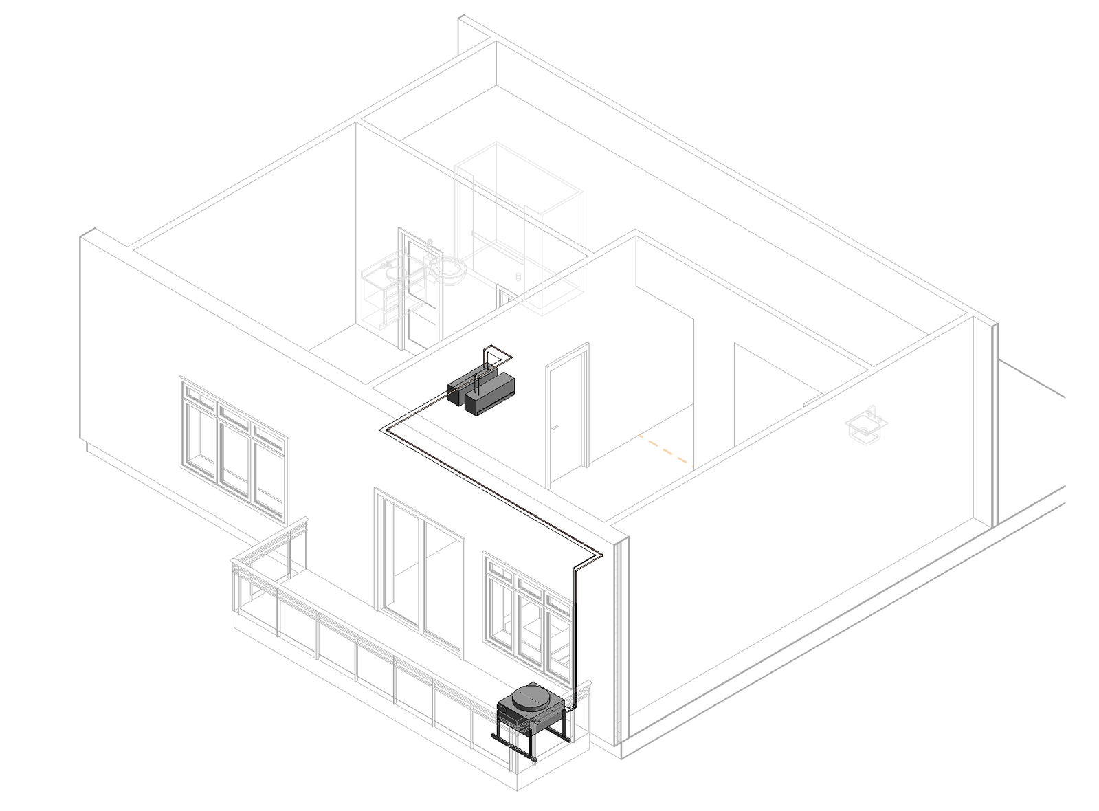
Note: The outdoor condenser unit could be located in a remote location — on a ground pad, a mechanical shelf, or on the roof.
You can download this file here:

AI Prompts
Creating a Ductless Mini-Split System
Prompt | Tool Options
🟢 = Autodesk Asst
🔵 = Revit MCP
🟣 = Python + Dynamo |
Add a ductless mini-split HVAC system to this residential apartment unit.
Cassettes:
• Place wall-mounted cassettes in the bedroom and living area on the central wall between the rooms.
Outdoor Unit:
• Place the outdoor condenser unit on the balcony to the far right side and model the refrigerant piping from the unit to the fan coil. | 🟣 |
Claude Response
I'll check the open Revit model, find the bedroom, living area, and balcony, then place the indoor units, outdoor condenser, and refrigerant piping.
Copper Type L refrigerant pipe is set up. Now building the wall-mounted indoor unit family (cassette body + liquid/suction connectors on top-rear) and loading it.
Family loaded. Now placing both indoor units back-to-back on the bedroom/living partition, the condenser at the far right of the balcony, and routing the liquid and suction lines.
That call timed out on your machine (it may be waiting for approval in Revit). Checking whether it ran before doing anything else, so nothing gets duplicated.
There's a second condenser (also marked CU-1) and some piping that were already in the model before I started. Looking at what they are.
That one's read-only, so retrying is safe.
The mini-split system is modeled, but there's one thing to settle before I call it done.
What's in the model now
- MS-1 Living and MS-2 Bedroom: wall-mounted ductless indoor units (32"W × 11"H × 9"D, bottom at 7'-6") hung back-to-back on the bedroom/living partition. They sit centered at the same spot on each face, about 5' south of the bedroom door, so they don't conflict with it. I built this family (Ductless Mini-Split – Wall Mounted Indoor Unit) because the project only had ducted fan coils. It has liquid and suction connectors on the top rear.
- CU-1: a 17 MBH air-cooled condenser at the far right of the balcony, with its connections facing the building.
- Refrigerant piping in Copper Type L, on the existing Refrigerant Liquid (1/4") and Refrigerant Suction (1/2") systems. The lines rise on the exterior face east of the living-room window, which works like a line-hide chase. They go through the exterior wall at 9'-6" and run along the living room's exterior wall and the partition. Each line tees down to the living unit and continues through the partition to the bedroom unit. All connections are made, there are no open ends, and the total run is about 99 ft.
A few things to note:
- The 17 MBH size and the pipe sizes are placeholders until a load calc is done. For a real dual-zone system you'd want a multi-zone outdoor unit or a manufacturer branch kit in place of plain tees.
- The partition the lines pass through is rated 2-hr, so those penetrations need firestopping.
- Condensate drains aren't modeled yet.
Example 2 - Ducted Mini-Split System
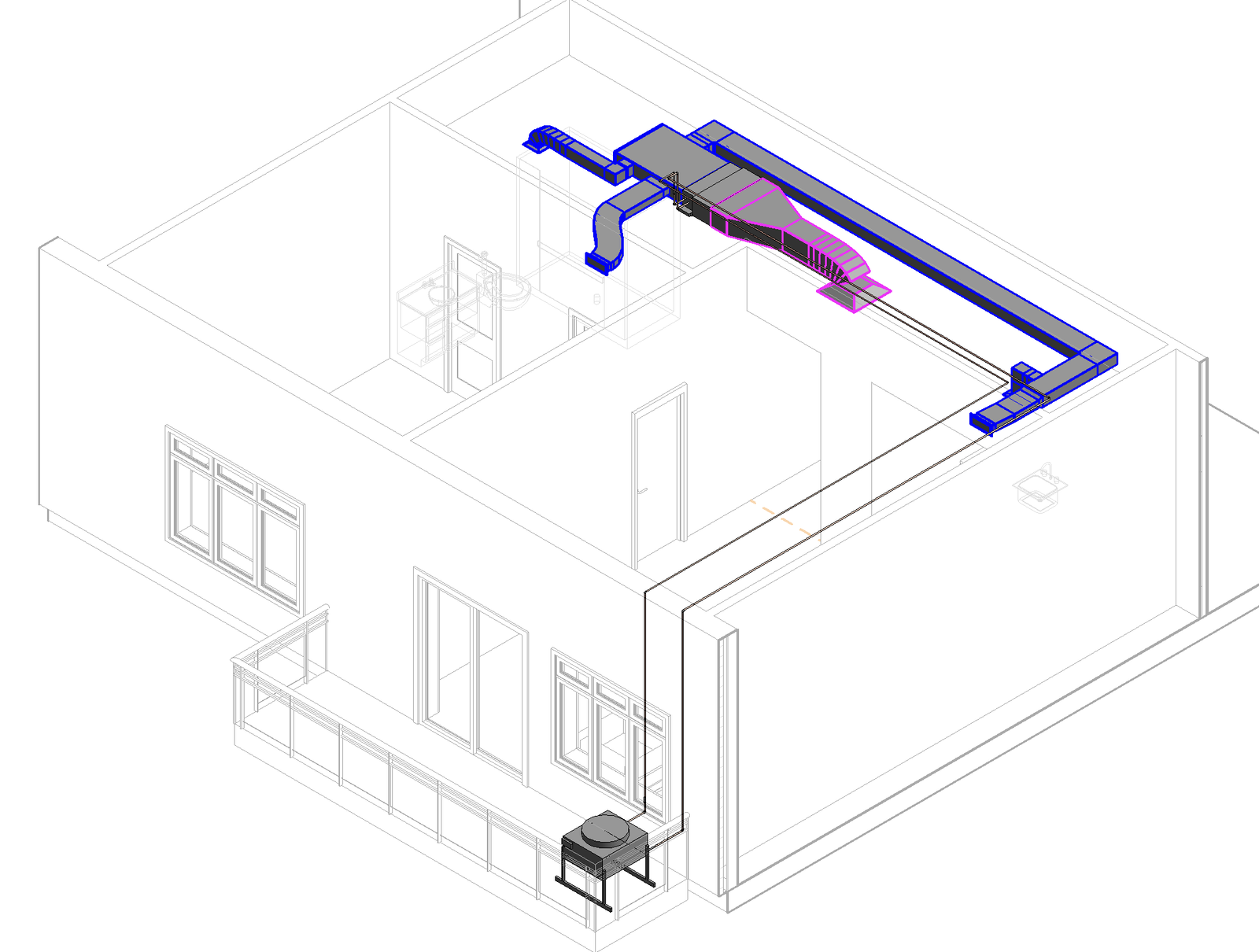
Note: The outdoor condenser unit could be located in a remote location — on a ground pad, a mechanical shelf, or on the roof.
You can download this file here:
AI Prompts
Creating a Ducted Mini-Split System
Prompt | Tool Options
🟢 = Autodesk Asst
🔵 = Revit MCP
🟣 = Python + Dynamo |
Add a ducted mini-split HVAC system to this residential apartment unit.
Fan Coil:
• Place the concealed duct fan coil unit in the space above the ceiling over the closet
Registers:
• Place a ceiling-mounted supply register in the center of the bathroom.
• Place a ceiling-mounted supply register in the center of the kitchen.
• Place a wall-mounted supply register at 10' high in the soffit wall between the closet and the bedroom.
• Place a wall-mounted supply register at 10' high in the soffit wall between the kitchen and living areas.
• Place a return register in the ceiling over the entry.
Ducts:
• Route supply ducts from the fan coil unit to the four supply registers.
• Route a return duct to the return register.
Outdoor Unit:
• Place the outdoor condenser unit on the balcony to the far right side and model the refrigerant piping from the unit to the fan coil. | 🟣 |
Claude Response
I'll connect to your open Revit model, find the closet, bathroom, kitchen, bedroom and living spaces, then place the duct unit and the four registers.
The model has no ducted mini-split family loaded, so I'll check your Revit content library for a concealed/horizontal fan-coil family before choosing.
Everything is in position. One last cleanup: the sidewall family pulled in ~500 types from its catalog, and I loaded a fan coil family I didn't end up using, so I'll remove those unused extras.
The ducted mini-split is now in your model (261030 Sample Apartment, Level L1). The changes are not saved yet.
Item | Family : Type | Location |
Concealed duct unit, Mark FCU-1 | Fan Coil Unit – Horizontal – DX : 600 CFM | Centered over the Closet, bottom at 9'-6" (top at about 10'-4"). It fits in the plenum between the 9' ceiling and the 12' level above. Its duct connection faces the bedroom. |
Bath register | Supply Diffuser – Square – Hosted : 10"×10" | Center of the Bath, hosted to the 9' ceiling |
Kitchen register | Supply Diffuser – Square – Hosted : 12"×12" | Center of the Kitchen, hosted to the 9' ceiling |
Closet/Bedroom wall register | Supply Diffuser – Sidewall : 12×4 | Centered at 10'-0" on the bedroom face of the closet/bedroom wall, aligned with the closet |
Kitchen/Living wall register | Supply Diffuser – Sidewall : 12×4 | Centered at 10'-0" on the living-room face of the kitchen/living soffit, aligned with the kitchen |
Things to check:
- Closet/bedroom "soffit": the closet/bedroom wall is a full-height 4½" partition (0'–12'), not a separate soffit wall like the one at the kitchen/living line. I put the register on it at 10'. That spot works because it sits above the closet's 9' ceiling, in the plenum.
- No ductwork or refrigerant piping yet, only the equipment and registers. The fan coil has a single supply connection, so you'll still need a return path, such as a return grille in the closet ceiling or door undercuts.
- Sizing is a placeholder. I picked 600 CFM (about 1.5 ton) for this unit of roughly 770 sf. Register sizes are typical, not calculated. Swap the types once the load calc is done.
- Families and cleanup: I loaded the families from your Revit 2027 imperial library. I also removed about 528 unused sidewall-diffuser catalog types that came in with that family.
A natural next step would be routing the supply ducts from FCU-1 to the four registers.
I'll map the plenum (ceiling outline and connector locations), check what duct types and systems are available, and sort out a return connection on the fan coil, since the current family only has a supply connection.
All runs connected. Next I'll cap the end of the supply header, then check for open connectors, system membership and warnings.
Both systems are fully connected: no open ends and no warnings. I'll do a quick visual check in 3D.
Supply and return ductwork are routed and fully connected. Both systems, "Supply Air – FCU-1" and "Return Air – FCU-1", report as well-connected, with no open ends and no model warnings. The changes are not saved yet.
Changes to the fan coil
- Unit swap: the original fan-coil family had no return connection. I swapped FCU-1 to Fan Coil Unit with Plenum – Horizontal – DX – Rear Return : 600 CFM and kept its Mark.
- Rotation: I turned it 90° so supply discharges west and return faces east toward the entry. It's still over the closet, bottom at about 9'-6", within the plenum.
Supply ductwork (rectangular with mitered elbows and taps; all ducts sit above the 9' ceiling)
- Plenum: a 31×8 plenum comes off the unit and is capped at the west end. Three taps come off it:
- Bath: 6×6 duct west, with a short 6×6 flex to the ceiling diffuser.
- Bedroom sidewall: 12×4 duct south, with a 12×4 flex to the register at 10'-0".
- Kitchen: 12×6 duct up to the north side of the plenum and east about 20' along the north wall, through the entry and into the kitchen. It then turns south.
- Kitchen diffuser: a 6×6 tap and a rigid drop off the kitchen run.
- Kitchen/living sidewall: the run steps down to 12×4 and connects with a short flex to the soffit register at 10'-0".
Return ductwork
- Grille: a new 24×24 ceiling return grille (Return Diffuser, 12×12 neck) in the entry. It's about 4" north of the room's center so it lines up with the unit.
- Duct: 12×12 duct from the grille west through the closet wall, with a transition to the unit's 33×10 return connection.
- Sizing note: this grille family locks its neck square, so I sized the return 12×12 (about 500 fpm) rather than the 20×10 I first intended.
For you to check
- Airflow: the system currently shows 500 CFM because the terminals carry default flows. Set the actual design CFM on each register and the return grille, then use Revit's sizing tool or a manual check to confirm the duct sizes.
- Bath tap stub: this segment is very short (about 1"), because the takeoff and elbow sit nearly back-to-back. It's valid, but you may want to nudge the bath branch.
- Wall penetrations: the 12×6 kitchen run passes through three partitions above the ceiling, one of them the 2-hr closet/living partition. Those will need penetrations, and possibly a fire damper at the rated wall.
- Not modeled: refrigerant piping, condensate and the outdoor unit.
I'll find the balcony, load a split-system outdoor unit from your library, and check the refrigerant connections on both units, plus the pipe types and systems available.
The liquid line routed. The suction line failed because its reducer points become straight, same-size joints where an elbow can't be inserted. I'll drop those points for the suction line and rerun.
The suction line is complete. The liquid line has a gap near the outdoor unit, probably at the reducer next to the condenser connection. I'll inspect that segment and the actual pipe diameters.
The outdoor unit is on the balcony and both refrigerant lines run from it to the fan coil, fully connected with no open ends or model warnings. The changes are not saved yet.
Outdoor unit (CU-1)
- Family: Condenser – Air Cooled – Vertical : 17 MBH (about 1.4 ton), sized to pair with the 600 CFM fan coil. It's a cooling condensing-unit family standing in for a mini-split heat pump outdoor unit. The heat-pump family in your library starts at 2.5 tons and labels its connections as hydronic, so it wouldn't match the fan coil.
- Location: east end of the balcony, about 6" in from the edge and 9" off the exterior wall. Its refrigerant connections face the building.
Refrigerant lines
- Systems: two new piping systems, "Refrigerant Liquid – CU-1/FCU-1" (3/8") and "Refrigerant Suction – CU-1/FCU-1" (5/8").
- Pipe: a new "Refrigerant" pipe type using Type L copper.
- Route:
- Out of the unit, then up the face of the exterior wall on the balcony.
- Through the wall at 11'-0".
- North about 18' along the east side of the living room.
- West about 21' at y ≈ 1.3–1.6'. This stays south of the kitchen/living soffit and crosses into the closet plenum.
- North under the fan coil, dropping into its refrigerant connections from the south.
- Lengths: about 51' liquid and 53' suction.
- Clearance: the lines stay above all ductwork, which tops out around 10'-5".
- Reducers: the equipment connections are 5/8" for both lines, so the liquid line has 5/8"×3/8" reducers on the vertical runs at each end.
For you to check
- Concealment over living: this model has no ceiling over the living room, so I assumed the 10' living ceiling leaves the 10'–12' zone for concealed piping. Confirm that zone is really available, or route the line set elsewhere.
- Exterior riser: the line set climbs about 10' up the balcony face of the exterior wall. In practice that would get a line-set cover. The wall penetration also needs sealing.
- Sizes: the line sizes are typical for about 1.5 tons. Confirm them, and the allowable line length, against the manufacturer's data. Revit lists Type L copper by nominal size, so 5/8" isn't a standard nominal size there.
- Not modeled: insulation on the suction line, the condensate drain (the fan coil's 7/8" drain connection is still open), and power and disconnects.