About Chilled Beams
A chilled beam system splits conditioning into two jobs. A dedicated outdoor air system (DOAS) supplies a small amount of dry, conditioned ventilation air. Chilled water at a relatively warm temperature, typically 57–62°F, removes the room's sensible heat at ceiling-mounted "beams." Because water carries most of the cooling, the air handler and ductwork can shrink to roughly a third to a fifth the size of a comparable all-air VAV system.
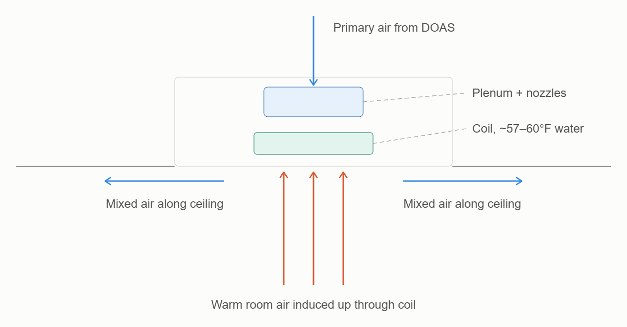
Here's a cross-section of an active chilled beam, the most common type.
How Chilled Beams Work
Primary air from the DOAS is ducted to a plenum inside the beam and forced through small nozzles at high velocity. The jets create a low-pressure zone that induces room air up through a chilled-water coil, typically at a ratio of about 2–5 parts room air for every 1 part primary air. The cooled room air mixes with the primary air and discharges along the ceiling through linear slots. It then spreads across the ceiling and drops gently into the occupied zone.
These have no duct connection and no fan. Warm room air rises to the beam, is cooled as it passes over the coil, becomes denser, and sinks back into the room by natural convection. Ventilation comes from a separate diffuser or displacement system.
These combine the coil with lighting, sprinkler heads, sensors, and speakers in one ceiling element.
- Chilled water: handles most of the sensible load (heat from people, equipment, lights, and solar gain). It can only remove sensible heat, because the coil must stay dry.
- Primary air: provides ventilation and must remove all of the latent load (moisture). The DOAS dries the air to a low dew point, typically 50–55°F, so the room stays dry enough for the beams to run without condensation.
Chilled Beam Connections
- Primary air duct: a small round connection, often 4–8", to each active beam, with a balancing damper. Passive beams have none.
- Chilled water supply and return: flexible hoses to the coil, with isolation valves and a control valve. The valve is usually a zone-level 2-way valve or a 6-way or pressure-independent valve serving a group of beams.
- Heating water, if used:
- In a 4-pipe beam, a separate hot water supply and return serve a second coil circuit.
- In a 2-pipe changeover system, one coil carries chilled or warm water depending on season.
- Controls:
- Zone temperature sensors modulate the water valves.
- Dew-point or condensation sensors (on the pipe or on the space) close the chilled-water valve or raise the water temperature if moisture is detected.
- Occupancy sensors can reset the primary airflow.
- No condensate drain: beams are designed to run dry. Some passive designs include a small drip tray as a backup.
How Chilled Beams Work in Different Conditions
The DOAS supplies cool, dry primary air at a roughly constant rate. The zone controller modulates the chilled-water valve to match the sensible load. Supply water is held a couple of degrees above the room dew point, usually by a dedicated mixing loop or a heat exchanger off the main chiller plant.
- Perimeter zones: warm water (about 95–120°F) flows through the beam coil, or through the 4-pipe heating circuit.
- Heating from ceiling beams works well for moderate loads in well-insulated buildings.
- In cold climates, or under tall glazing, beams for heating can stratify warm air near the ceiling. Designers often add perimeter radiation or limit beam heating to modest outputs.
Handled entirely by the DOAS, through deep cooling coils, desiccant wheels, or energy recovery wheels with reheat. If the space dew point rises (say, from an open window or a crowded room), the controls cut chilled-water flow to prevent sweating. Cooling capacity drops temporarily until the DOAS catches up.
Primary air can drop to minimum or shut off. Water valves remain available for setback cooling or heating, and the DOAS may run a pre-occupancy dehumidification cycle in humid climates.
Pros and Cons of Chilled Beam Systems
- Energy savings: fan energy drops sharply because the system moves only ventilation-sized air volumes. Pumps move most of the heat, and pumping is far cheaper than fan power.
- Chiller efficiency: warm chilled water (57–62°F) raises chiller efficiency and allows more water-side economizer hours.
- Smaller ductwork and AHUs: frees floor-to-floor height, shaft space, and mechanical room area. This is valuable in retrofits and tall buildings.
- Quiet: no fans at the zone. Active beams make only light nozzle noise when properly sized.
- Comfort: low air velocities, even temperatures, no cold dumping from diffusers.
- Low maintenance: no filters, fans, motors, or drain pans at the zone. Coils only need occasional vacuuming, typically every 3–5 years.
- Hygiene: dry coils with no wet surfaces or drain pans reduce microbial growth risk.
- Ventilation clarity: 100% outside air at a known rate makes ventilation compliance and IAQ control straightforward.
- Condensation risk: the system depends on tight humidity control. Operable windows, poor envelopes, and DOAS failures can force beams offline.
- Capacity limits: typically around 30–40 Btu/h per square foot of floor area for active beams. High-load spaces like dense meeting rooms, kitchens, and server rooms may exceed what beams can handle.
- Weak heating in cold climates: ceiling heat stratifies, so supplemental perimeter heat is often needed.
- First cost: beams, extra piping, and the DOAS can cost more than a basic VAV system. Savings come from lower operating costs and reduced building height or volume.
- Ceiling coordination: beams occupy ceiling area and need water piping above every one.
- Leak risk: water runs above occupied spaces, with many hose connections.
- Inflexible layouts: reconfiguring spaces means moving beams and piping, which is harder than relocating a VAV diffuser.
- Design and commissioning expertise: requires designers and contractors familiar with dew-point control, induction ratios, and dedicated water loops.
Comparison with other HVAC strategies
Chilled beams + DOAS | VAV (all-air) | Fan coils + DOAS | WSHP / VRF + DOAS | Radiant ceiling + DOAS | |
Heat transport | Mostly water | Air | Water to zone, fan at zone | Refrigerant or water loop | Water |
Zone fans | None | None (central fan) | Yes | Yes | None |
Duct size | Small | Large | Small | Small | Small |
Cooling capacity per ft² | Moderate | High | High | High | Low–moderate |
Latent handling at the zone | None (DOAS only) | Yes | Yes (wet coil + drain) | Yes (wet coil + drain) | None (DOAS only) |
Noise | Very low | Low–moderate | Moderate | Moderate | Silent |
Zone maintenance | Very low | Low (VAV box) | Filters, fans, drain pans | Compressors, filters, drain pans | Very low |
Energy | Very good | Fair–good (reheat, fan energy) | Good | Good–very good (heat recovery) | Very good |
Reconfiguration | Harder | Easy | Moderate | Moderate | Harder |
First cost | Moderate–high | Lowest–moderate | Moderate | Moderate–high | High |
Humidity tolerance | Low | High | High | High | Low |
Where Chilled Beams Fit Best
- Offices with moderate, steady loads and well-sealed envelopes
- Laboratories, where high ventilation rates already require large primary air volumes and beams add cooling without increasing airflow
- Hospitals (patient rooms, clinics), where quiet, low-maintenance, drain-free zones help infection control
- Schools and universities: classrooms, libraries, offices
- Retrofits with limited ceiling or shaft space, where existing ducts can't support an all-air system
- Dry climates, where dew point is easy to control and water-side economizer hours are long
- Hot, humid climates: workable with a strong DOAS, but the dehumidification equipment becomes critical
- Buildings with operable windows, unless window contacts automatically shut off chilled water
- Perimeter heating in cold climates: plan for supplemental heat
- High-latent or high-sensible spaces: kitchens, natatoriums, gyms, crowded assembly halls, data closets
- Spaces with frequent layout changes or open ceilings with no coordination budget
- Small buildings where a separate DOAS and water plant isn't economical
Bottom line: Chilled beams make the most sense in buildings with moderate loads, good envelopes, and real value placed on quiet, low-maintenance zones and reduced building volume. The DOAS is what makes the whole system work, so its dehumidification performance and reliability deserve as much design attention as the beams.
Example - Chilled Beam Systems
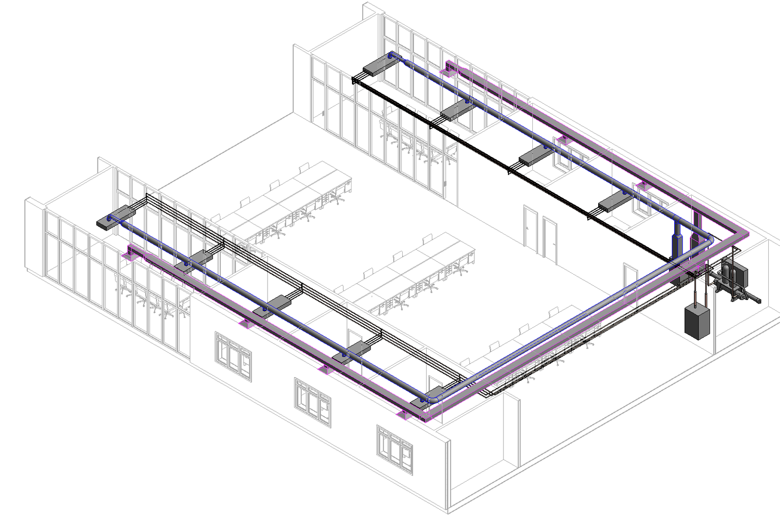
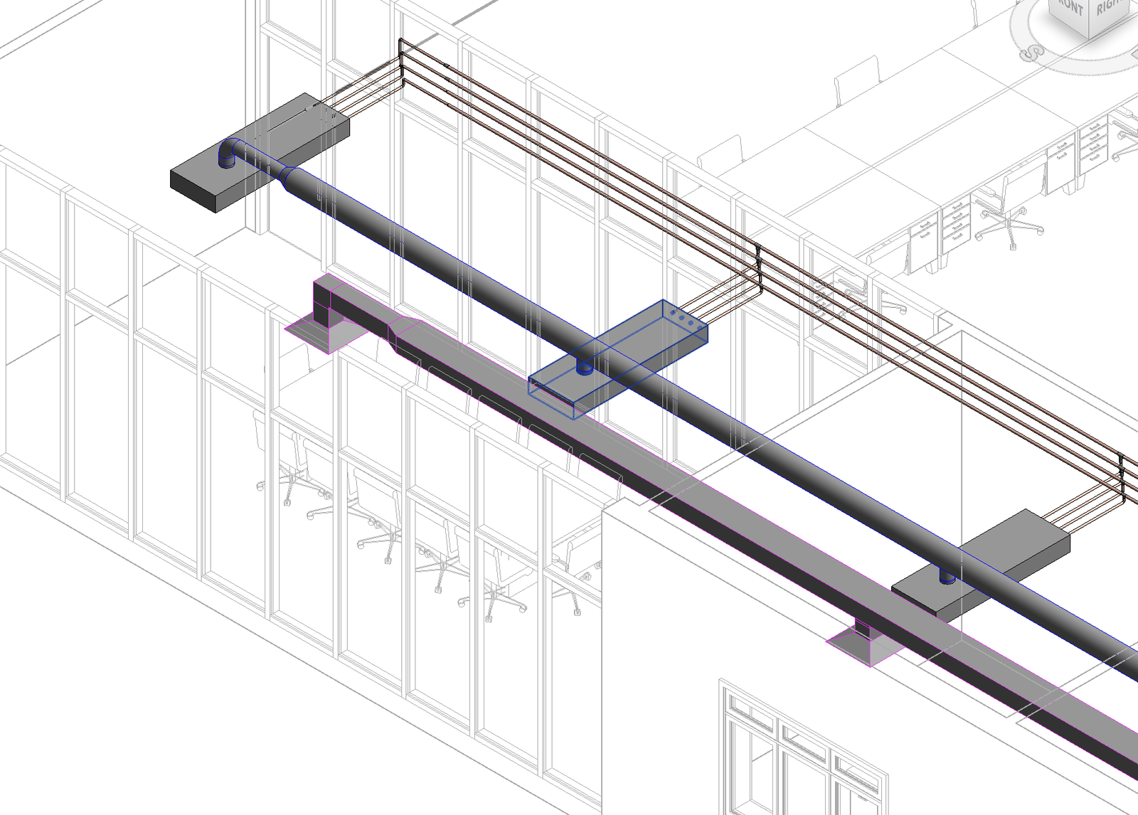
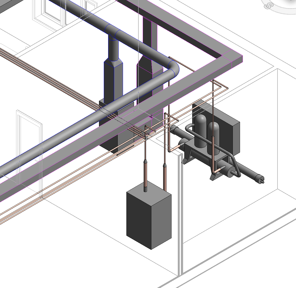
Note: The mechanical room and its equipment could be located remotely.
You can download this file here:

AI Prompts
Creating a Chilled Beam System
Prompt | Tool Options
🟢 = Autodesk Asst
🔵 = Revit MCP
🟣 = Python + Dynamo |
Add an active chilled beam system to the offices and conference rooms in this office layout.
Chilled Beams:
• Place ceiling-mounted chilled beams at 10’ above the floor level in the offices and conference rooms.
• Place 1 chilled beam and a return air intake in each office.
• Place 2 chilled beams and a return air intake in each conference room.
Water & Air Sources:
• Route the air supply ducts and return air ducts to an air handler unit in the mechanical room at the northeast corner of the layout.
• Route the hot and cold water piping to a boiler and a chilled water unit in the same mechanical room. | 🟣 |
Claude Response
I'll check the open Revit model to find the offices, conference rooms and mechanical room, then lay out the chilled beams, ductwork and piping.
No chilled beam or chiller family is loaded, so I'll look in the local Revit content library for them.
Beam family built and loaded. Next, loading a chiller and placing the AHU, boiler and chiller in the mechanical room.
Done so far in "261102 Sample Office":
- Built a 2'×6' 4-pipe active chilled beam family (6" primary-air connection on top; ¾" CHWS/CHWR/HWS/HWR connections on one end), saved to
Documents\Revit Families\Active Chilled Beam - 4 Pipe.rfa, and loaded it. - Placed 9 chilled beams at 10'-0" AFF: 1 in each of the 5 offices (3 south, 2 north) and 2 in each conference room (north and south), marked CB-1 to CB-9.
- Placed 7 return grilles (RG-1 to RG-7), one per office and conference room, near the exterior wall.
- Put an AHU, boiler and water-cooled scroll chiller in the NE mechanical room, arranged so they fit (chiller along the north wall, boiler in the SE corner, AHU on the west side).
- Created Chilled Water Supply/Return and Heating Hot Water Supply/Return piping system types.
Still to do once Revit responds:
- The script that may be waiting for approval switches the grilles to a 12×8 neck so they fit in the plenum. It's safe to approve.
- Then I'll route the ductwork (10" round supply main and 14×8 return main) and the four water mains back to the mechanical room, connect everything, and check for open connectors and clashes.
One thing to know before routing: with the beams at 10' and L2 at 12', there's only about 2' of plenum. I'm stacking the pipes just above the beams and the ducts at the top. That works as a coordination model, but it will be very tight once you add real slab depth and insulation.
The grille family locks its neck square, so I'll use an 8×8 neck (still fine for these airflows — roughly 300–450 fpm). Now routing the supply air.
Supply air is fully connected. Now the return air.
All piping routed without failures. Now verifying: open connectors, system membership, and model warnings.
The active chilled beam system is fully modeled and saved in "261102 Sample Office". Every network is fully connected, and the model shows no warnings.
Chilled beams and returns
- There are 9 chilled beams, each 2'×6', 4-pipe, with the bottom at 10'-0" AFF:
- one in each of the 5 offices (CB-3, CB-4, CB-5, CB-8, CB-9)
- two in each conference room (CB-1/CB-2 in the south room, CB-6/CB-7 in the north room)
- There are 7 return grilles (RG-1 to RG-7), one in each office and conference room, near the exterior wall.
Air
- Supply air: a 10" round main runs over the beams in both wings and back to the AHU. Each beam gets a 6" drop, and a rectangular-to-round riser connects the main to the AHU.
- Return air: a 14×8 main runs along the exterior side of the rooms. Each grille connects with an 8×8 drop, and a 22×15 riser connects the main to the AHU return.
Water
- Chilled water supply and return run to a water-cooled scroll chiller.
- Heating hot water supply and return run to the boiler.
- Each service has 1" mains in the open office and ¾" branches to each beam. The pipes reduce from the equipment's 2" or 3" connections on the risers.
- The four services sit at different elevations (10.6', 10.74', 10.88' and 11.02'), so they cross without clashing.
Mechanical room
- The chiller is along the north wall, the boiler is in the SE corner, and the AHU is on the west side.
Things to know
- The plenum is only about 2', because the beams are at 10' and L2 is at 12'. The supply duct tops out around 11'-11", so this layout won't survive once real slab depth and insulation are added.
- Sizes are placeholders and haven't been sized to actual loads. I assumed about 100 cfm and 1.5 gpm per beam.
- Some connections are left open on purpose, because they're outside what you asked for:
- the chiller's condenser-water and drain connections
- the AHU's refrigerant and condensate connections
- The beam is a generic family I built. It's saved at
Documents\Revit Families\Active Chilled Beam - 4 Pipe.rfa, and a manufacturer's family can be swapped in later.
A useful next step would be sizing the ducts and pipes to actual loads, or adding condenser water and a cooling tower connection for the chiller.