Working links to all three models in Forma Data Management and your Forma Board
PDF sheet set at E1 size, 30 by 42 inches
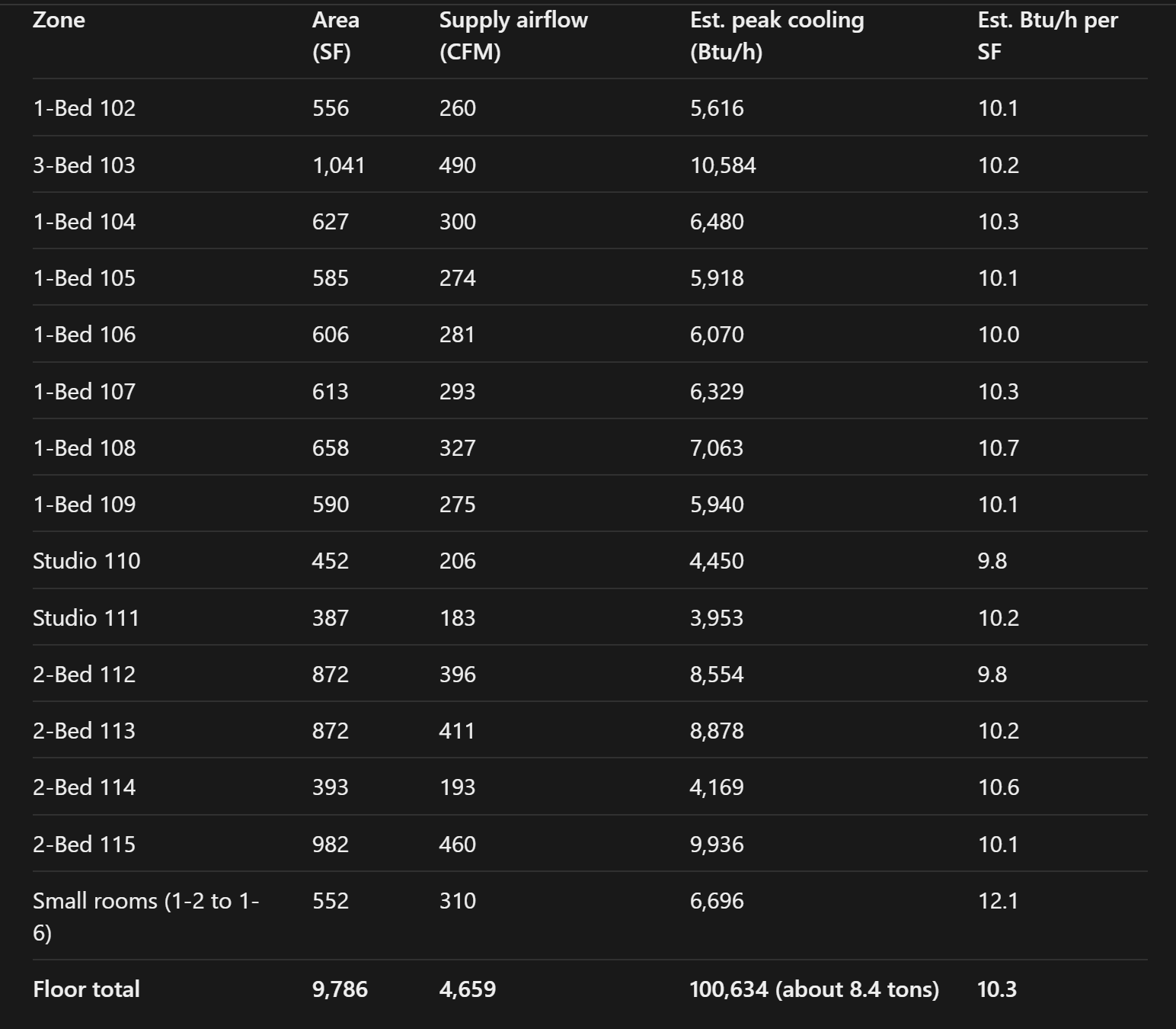
Load summary table: floor total and by zone
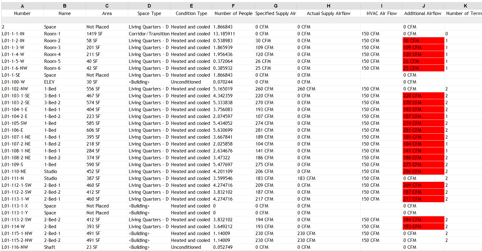
Alternatives comparison: your representative unit and your alternative unit, compared by numbers, with your conclusion
Please paste your two alternatives comparison here, what differs between them, and which you choose and why…
Below is both text blocks, ready to paste. One thing first, because it changes the comparison: your model shows both fan coils in the corridor band (Studio 111’s at y 257 to 260, 1-Bed 102’s at y 256 to 259), so fan coil location is not what differs. What differs is the unit size, the airflow and the branch layout. The text below says that honestly. If the alternative really is meant to have its fan coil inside the unit, move it first and tell me, and I’ll redo the numbers.
Alternatives comparison
Representative unit (Studio 111) vs. alternative unit (1-Bed 102)
Metric | Studio 111 | 1-Bed 102 |
Area | 387 SF | 556 SF |
Supply airflow | 183 CFM | 260 CFM |
Total duct length | 39.8 ft | 59.0 ft |
Duct length per CFM | 0.217 ft/CFM | 0.227 ft/CFM |
Trunk (size, velocity) | 7" x 7", 539 FPM | 8" x 8", 585 FPM |
Highest branch velocity | 437 FPM | 382 FPM |
Branch length | 10.0 ft | 17.6 ft |
Refrigerant line set | 87.8 ft | 87.8 ft |
What differs: the alternative is a larger unit (556 vs. 387 SF) with more airflow (260 vs. 183 CFM). Its trunk is about 4 ft longer, its branches run 17.6 ft instead of 10.0 ft because its diffusers sit farther from the fan coil, and its trunk is one size larger. The refrigerant line is the same length for both, since each condenser sits directly above its unit. Both fan coils sit above the corridor wall.
Conclusion: “The two layouts are close per unit of airflow (0.217 vs. 0.227 ft of duct per CFM), so neither is much more efficient. I choose the representative layout, with the fan coil close to its diffusers, because its branches are shorter, its trunk velocity is lower (539 vs. 585 FPM), and shorter runs mean less pressure drop and less plenum space. The alternative’s longer branches are the cost of a larger unit, not a better arrangement.”
Design memo of 300 to 500 words: your strategy and why, what the loads told you about your envelope, where your structure got in the way, and what you left unresolved
Strategy. I gave each modeled unit its own DX fan coil, supply trunk and return grille, with a roof-mounted air-cooled condenser, instead of a shared duct system. Apartments need independent control, and the ceiling plenum is too shallow for large mains. Studio 111 is a single zone. 2-Bed 115 has two zones, so each half has its own branch and a control damper, with 115 CFM at each of its four diffusers. 1-Bed 102 is the alternative. I sized each supply system with Friction and Velocity at about 0.08 in. per 100 ft and 700 FPM, so the trunks came out 7 to 10 inches square.
What the loads told me. The design airflow averages 0.48 CFM per SF over the 9,786 SF of apartment space, which is roughly 10 Btu/h per SF of cooling at a 20 °F supply temperature difference (my estimate, not a report value). That is low, so the envelope and internal gains are doing little work in these units. The ventilation minimum (0.03 CFM/SF plus 7.5 CFM per person) never controlled, and even the tightest unit sat about 5.6 times above it, so loads set the design. The default Living Quarters lighting of 1.10 W/ft² is office-like and overstates cooling in apartments, so I corrected occupancy to bedrooms plus one per unit.
Where structure got in the way. The plenum was the main constraint. The ceiling is at 8'-0" and the trunk ran at 9'-0" middle elevation, so a 12-inch duct left little vertical room. Each diffuser connects through a stub only 1 inch long, which blocked automatic sizing, because a transition needs more room than that. I raised the last branch of each system by 6 inches so the stubs became 7 inches, and sizing then worked. [Add where beams or the corridor wall limited the trunk, from your plenum section.]
What I left unresolved. Refrigerant piping isn’t modeled; each line set would run about 63 ft vertical plus 14 to 25 ft horizontal. The fan coil family is Bottom Return, not Rear Return. The load results didn’t write back to the spaces, so my cooling column is an estimate and I have no peak heating numbers. The return grilles sit at about 10'-10" in the corridor ceiling, and no ERV was modeled.