Working links to all three models in Forma Data Management and your Forma Board
Architectural

Structural
Mechanical
Forma Board
PDF sheet set at E1 size, 30 by 42 inches
Please paste your PDF sheet set here…
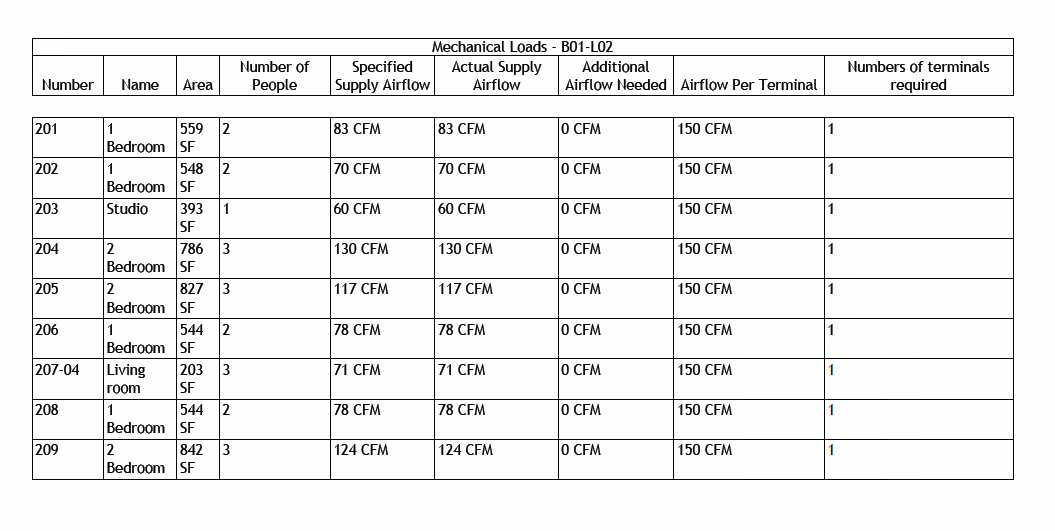
Load summary table: floor total and by zone
Please paste your load summary table here…
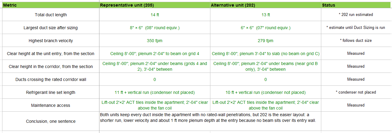
Alternatives comparison: your representative unit and your alternative unit, compared by numbers, with your conclusion
Please paste your two alternatives comparison here, what differs between them, and which you choose and why…
Design memo of 300 to 500 words: your strategy and why, what the loads told you about your envelope, where your structure got in the way, and what you left unresolved
Please paste your design memo here…
This strategy started in Module 2. Because of the W270 wind, we placed the corridor on that side to act as a barrier against the wind and cold. This layout maximizes sunlight hours, keeping the apartments in the zone that gets direct sun for natural heating. By addressing environmental factors first, the mechanical systems require less effort to maintain baseline temperatures. For this mechanical analysis, I chose Level 2 (B01-L02) as the typical floor. It accurately represents the standard residential layout and the baseline thermal profile. Sandwiched between other conditioned floors, it is isolated from the ground floor's thermal bridging and the roof's solar heat gain. This makes it an ideal control model for resolving spatial coordination and routing issues. The load summary highlights the envelope's impact on energy demands. While Unit 201 (corner) and Unit 202 (interior) are both 1-bedroom apartments with similar areas (559 SF and 548 SF, respectively), their required airflows differ. Unit 201 needs 83 CFM, whereas Unit 202 only requires 70 CFM. This 19% increase is driven entirely by Unit 201's corner exposure. These loads indicate that current facade performance demands higher conditioning at the building's extremities, meaning targeted thermal resistance upgrades at the corners could optimize our mechanical sizing. During spatial coordination, the structural system presented significant constraints within the ceiling plenum. The plenum section (M005) for the Unit 202 Lobby and Unit 205 Corridor shows extremely tight vertical clearance between the drop ceiling and the structural slab. Routing rigid ductwork horizontally required strict elevation control to avoid clashes with the framing without compromising architectural clear heights. Navigating these structural pinch points without introducing excessive bends was our primary constructability challenge.