Please enter the following info in the fields above:
- Link to Student (type the first few letter of your name, then select yourself in the list of linked records)
What to Submit
- Working links to all five models in Forma Data Management (architectural, structural, mechanical, plumbing and electrical) and your Individual Forma Board.
- PDF sheet set at E1 size, 30 by 42 inches, four sheets: plumbing plan, riser section showing the sanitary fall, power plan, lighting plan.
- Your illumination spot check result.
- Design memo of 300 to 500 words: where the sanitary riser went and why, what gravity forced you to change, whether your daylighting reduced your lighting load, and what you left unresolved.
Working links to all five models in Forma Data Management (architectural, structural, mechanical, plumbing and electrical) and your Individual Forma Board
plumbing: https://acc.autodesk.com/docs/files/projects/44ee68f0-3782-4cbd-b6c0-af2ff94ead94?folderUrn=urn%3Aadsk.wipprod%3Afs.folder%3Aco.EOl-rojMTdC7y0tcu0p3uA&entityId=urn%3Aadsk.wipprod%3Adm.lineage%3Ap-NXi0a2RZ6dxgXDC0N00A&viewModel=detail&moduleId=folders
electric: https://acc.autodesk.com/docs/files/projects/44ee68f0-3782-4cbd-b6c0-af2ff94ead94?folderUrn=urn%3Aadsk.wipprod%3Afs.folder%3Aco.EOl-rojMTdC7y0tcu0p3uA&entityId=urn%3Aadsk.wipprod%3Adm.lineage%3ANPabovo_Rve5YEW_kUmjJw&viewModel=detail&moduleId=folders
mech: https://acc.autodesk.com/docs/files/projects/44ee68f0-3782-4cbd-b6c0-af2ff94ead94?folderUrn=urn%3Aadsk.wipprod%3Afs.folder%3Aco.sEOk2CX8QdOXHGecNutjSA&entityId=urn%3Aadsk.wipprod%3Adm.lineage%3Ac6Lf4phGQyyjsWrU2gcUPw&viewModel=detail&moduleId=folders
arch:https://acc.autodesk.com/docs/files/projects/44ee68f0-3782-4cbd-b6c0-af2ff94ead94?folderUrn=urn%3Aadsk.wipprod%3Afs.folder%3Aco.sEOk2CX8QdOXHGecNutjSA&entityId=urn%3Aadsk.wipprod%3Adm.lineage%3ApIf5B8i1SNCI89nLuLnjbQ&viewModel=detail&moduleId=folders
structural:https://acc.autodesk.com/docs/files/projects/44ee68f0-3782-4cbd-b6c0-af2ff94ead94?folderUrn=urn%3Aadsk.wipprod%3Afs.folder%3Aco.sEOk2CX8QdOXHGecNutjSA&entityId=urn%3Aadsk.wipprod%3Adm.lineage%3A0o4cV2etQ1GMjvY4nHs3Cw&viewModel=detail&moduleId=folders
PDF sheet set at E1 size, 30 by 42 inches, four sheets: plumbing plan, riser section showing the sanitary fall, power plan, lighting plan
Your illumination spot check result
Illumination spot check: Kitchen, Unit 112 (112-KIT)
Item | Value |
Space | 112-KIT Kitchen, 94 SF |
Fixtures | 4 recessed downlights, 8" cans, ceiling-mounted at 8'-0" |
Workplane | 3'-0" (counter height) |
Reflectances | Ceiling 75% / Walls 50% / Floor 20% |
Average estimated illumination | 428 lux (≈ 40 fc) |
Target | 215 to 558 lux (residential kitchen, IES-based range) |
Result | Passes, mid-range |
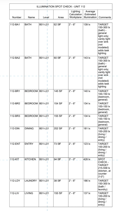
Method: Revit’s lumen-method calculation on the electrical space (Average Estimated Illumination). Daylight is not included. The first pass with standard cans gave 210 lux, just under target, so I upgraded the kitchen to higher-output 8" cans; LED equivalents with the same lumen output are specified per Title 24.
Rest of unit 112 for reference: bedrooms 134 to 140 lx (target 100 to 150), dining 181 lx and entry 123 lx (target 100 to 200), laundry 186 lx (target 150 to 300), baths 139 to 143 lx (target 150 to 300; a vanity light, not modeled, covers task lighting).
Design memo of 300 to 500 words: where the sanitary riser went and why, what gravity forced you to change, whether your daylighting reduced your lighting load, and what you left unresolved
Where the sanitary riser went and why. I placed the sanitary riser, with the vent, hot water, and cold water risers beside it, in the 5" north wall of bath 112-BA1, between the tub’s valve end and the toilet. That position puts every fixture within 3.5 feet of its riser, so the branches stay short and the drains need little fall. The bath repeats directly above itself on Floors 2 and 3, so the stack drops straight to the ground-floor trunks with no offsets. A script checked the riser path and found no beams, only the 6¾" floor slabs, which need firestopping at each penetration.
What gravity forced me to change. Drains cannot run inside the floor, so both fixture drains drop through the slab and run in the ceiling of the floor below: the toilet branch about 10 inches below the finished floor and the tub branch about 18. I modeled them flat, as the brief allows, but at the code minimum of ¼" per foot, the 3.5-foot tub run needs about 1 more inch of fall, taken from the ceiling below. Gravity also exposed the wall. A 3" sanitary stack measures 3.5" outside, and the toilet’s cold water line passes behind it with only 0.1" of clearance. The fix is a 6" wet wall, which I would carry back into the architectural model.
Whether my daylighting reduced my lighting load. It did not reduce the fixture count. Revit’s illumination calculation ignores daylight, and apartments need full light at night, so the design has to work in the dark. My first pass with standard cans gave only 58 to 137 lux, so I upgraded most rooms to 8" cans. The kitchen spot check now reads 428 lux at counter height against a 215 to 558 lux target. The 32% window-to-wall ratio and the balconies can still cut energy use: the living and dining cans could sit on daylight dimming controls. On the panel, the area-based estimate of 1,442 SF × 3 W/SF gives 4,326 VA, against 5,248 VA modeled. LED cans, which Title 24 requires, would bring the modeled load close to the estimate.
What I left unresolved. I did not model drain slope, trap arms, or vent connections to the drains, and the pipes stop at each fixture connector without snapping because of a Revit connectivity error. The bathroom walls on Floors 2 and 3 are missing, so the upper risers stand in open space. On the electrical side, I left out the feeder from the building’s main switchboard to panel LP-112, 240V circuits for a dryer and range, the heat pump condenser’s circuit, and vanity lights in both baths, which sit just under their 150 lux target. My five models share coordinates but are copies rather than links, as my setup note explains.
Illumination spot check: Kitchen, Unit 112 (112-KIT)
Item | Value |
Space | 112-KIT Kitchen, 94 SF |
Fixtures | 4 recessed downlights, 8" cans, ceiling-mounted at 8'-0" |
Workplane | 3'-0" (counter height) |
Reflectances | Ceiling 75% / Walls 50% / Floor 20% |
Average estimated illumination | 428 lux (≈ 40 fc) |
Target | 215 to 558 lux (residential kitchen, IES-based range) |
Result | Passes, mid-range |
Method: Revit’s lumen-method calculation on the electrical space (Average Estimated Illumination). Daylight is not included. The first pass with standard cans gave 210 lux, just under target, so I upgraded the kitchen to higher-output 8" cans; LED equivalents with the same lumen output are specified per Title 24.
Rest of unit 112 for reference: bedrooms 134 to 140 lx (target 100 to 150), dining 181 lx and entry 123 lx (target 100 to 200), laundry 186 lx (target 150 to 300), baths 139 to 143 lx (target 150 to 300; a vanity light, not modeled, covers task lighting).